DriverID Selector Switch: Difference between revisions
No edit summary |
|||
| Line 20: | Line 20: | ||
[[image:Resister.png|400px]] | [[image:Resister.png|400px]] | ||
'''Resistors | '''[https://amzn.to/2ubkvCX Resistors:]''' | ||
You can use any value resister you want, but they all need to be the same value. Recommend 1k-100K range. You need '''total number of drivers - 1''' resisters. Ie if you have a 6 driver switch, you need 5 resistors (all same value). If you have 4 driver switch, you need 3 resistors, etc. | |||
==Wiring== | ==Wiring== | ||
| Line 121: | Line 30: | ||
[[image:DriverSelectorSwitchAnotated.jpg|800px]] | [[image:DriverSelectorSwitchAnotated.jpg|800px]] | ||
*Solder the resister for Driver 2 between switch position 1 and switch position 2, down low on the posts | *Solder the resister for Driver 2 between switch position 1 and switch position 2, down low on the posts | ||
*Solder the resister for Driver 4 between switch position 3 and switch position 4, down low on the posts | *Solder the resister for Driver 4 between switch position 3 and switch position 4, down low on the posts | ||
| Line 127: | Line 35: | ||
*Solder the resister for Driver 3 between switch position 2 and switch position 3, up high on the posts | *Solder the resister for Driver 3 between switch position 2 and switch position 3, up high on the posts | ||
*Solder the resister for Driver 5 between switch position 4 and switch position 5, up high on the posts | *Solder the resister for Driver 5 between switch position 4 and switch position 5, up high on the posts | ||
*Solder | *Solder Ground wire to switch position 1 post. | ||
*Solder 5V Input wire to last switch position post | |||
*Solder | *Solder Voltage Out wire to the center post, this goes to RCP analog input. | ||
*Solder | |||
*Use heat shrink tube to protect the wires | *Use heat shrink tube to protect the wires | ||
| Line 136: | Line 43: | ||
[[image:DriverSelectorSwitchAnotated2.jpg|400px]] [[image:DriverSelectorSwitch3.jpg|400px]] | [[image:DriverSelectorSwitchAnotated2.jpg|400px]] [[image:DriverSelectorSwitch3.jpg|400px]] | ||
Install the switch and wire the ground wire (black in pics above) to ground. The wire with the 10K resister is the 5V In (yellow in pics above), wire it to 5V Ref. The other wire connected to the Driver 1 resister (white wire in pics above) goes to an RCP Analog Input. | Install the switch and wire the ground wire (black in pics above) to ground. The wire with the 10K resister is the 5V In (yellow in pics above), wire it to 5V Ref. The other wire connected to the Driver 1 resister (white or red wire in pics above) goes to an RCP Analog Input. | ||
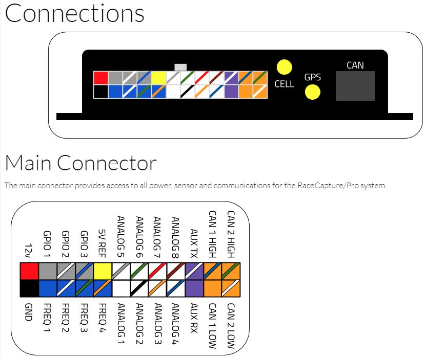
[[image:RCPInputs.jpg|link=RacecapturePro_MK3_hardware_install#Connections]] | [[image:RCPInputs.jpg|link=RacecapturePro_MK3_hardware_install#Connections]] | ||
| Line 148: | Line 55: | ||
For Mode, select Mapped. | For Mode, select Mapped. | ||
If you have | The first position will always be 0v and the last postiton on the switch will always be 5V. Take the number of resisters you used and divide that by 5V to get the voltage spread between the positions on the switch. Use this number to figure out what the voltage value for the positions in the middle should be. If you have more than 5 mapped values, use the 1st, 2nd, last, 2nd from last and one somewhere in the middle. If you have less than 5 mappings, just copy the last mapped settings to the rest of the mapped value pairs. | ||
[[image:RaceCaptureSwitchMappings.png]] | [[image:RaceCaptureSwitchMappings.png]] | ||
Revision as of 22:04, 19 February 2020
DriverID Selector Switch allows you to easily select which driver is driving so that you can quickly and easily see who was driving in the data later by looking at the DriverID channel. Just assign each driver a number, and tell them to turn the switch to their number when they get in.
{{#evu:https://www.youtube.com/watch?v=vGHrShqMUa4}}
Parts Needed:

1 pole Selector Switch (chose one):
- 2 Position Switch - $10
- 3 Position Switch - Currently NA
- 4 Position Switch - $6
- 5 Position Switch - $10
- 6 Position Switch - $10
- 7 Position Switch - Currently NA
- 8 Position Switch - $10
- 10 Position Switch - $10

You can use any value resister you want, but they all need to be the same value. Recommend 1k-100K range. You need total number of drivers - 1 resisters. Ie if you have a 6 driver switch, you need 5 resistors (all same value). If you have 4 driver switch, you need 3 resistors, etc.
Wiring


- Solder the resister for Driver 2 between switch position 1 and switch position 2, down low on the posts
- Solder the resister for Driver 4 between switch position 3 and switch position 4, down low on the posts
- Solder the resister for Driver 6 between switch position 5 and switch position 6, down low on the posts
- Solder the resister for Driver 3 between switch position 2 and switch position 3, up high on the posts
- Solder the resister for Driver 5 between switch position 4 and switch position 5, up high on the posts
- Solder Ground wire to switch position 1 post.
- Solder 5V Input wire to last switch position post
- Solder Voltage Out wire to the center post, this goes to RCP analog input.
- Use heat shrink tube to protect the wires


Install the switch and wire the ground wire (black in pics above) to ground. The wire with the 10K resister is the 5V In (yellow in pics above), wire it to 5V Ref. The other wire connected to the Driver 1 resister (white or red wire in pics above) goes to an RCP Analog Input.
Race Capture Settings
Edit the Analog input channel that you wired the DriverID Switch to. Click the gear icon and change the name to DriverID, set Precision to 0, Min to 0, and Max to however many positions your switch has. Set the Sample Rate to 1Hz.

For Mode, select Mapped.
The first position will always be 0v and the last postiton on the switch will always be 5V. Take the number of resisters you used and divide that by 5V to get the voltage spread between the positions on the switch. Use this number to figure out what the voltage value for the positions in the middle should be. If you have more than 5 mapped values, use the 1st, 2nd, last, 2nd from last and one somewhere in the middle. If you have less than 5 mappings, just copy the last mapped settings to the rest of the mapped value pairs.

Write the config to Race Capture and test the switch with the dashboard.
If it does not work properly, go back to the settings, change Precision to 2 and change the Mode to Raw. Write the config, and test again. Write down the Voltage for each position on the switch. If any do not match up with what is in the table above, go back and input that value in the Race Capture mapping table in an appropriate cell location. Change the Precision back to 0 and Mode back to Mapped and test again. Rinse and repeat.
See the Calibrating Sensors Guide for more info on how to map sensors properly.