CAN Crossover Cable
- Written by Scott Barton of ProFormance Coaching
Most of Autosport Labs CAN device cables are wired to CAN Bus Channel 1. This can be a problem if you want to integrate 2 or more CAN systems that run at a different baud rate, or if they interfere with each other. For example AIM CAN bus baud rate is 1M and OBDII baud rate is 500k. You can add both of these 2 CAN devices/systems to a Race Capture device with an RJ45 Splitter. Problem is the stock ASL AIM to RCP cable is wired to CAN 1 and the ASL OBDII cable is also wired to CAN 1. These two devices cannot be on the same CAN channel because they use different baud rates. You can easily build an RJ45 CAN Crossover cable to swap the CAN 1 and CAN 2 channel wiring for that CAN device/system. You can either permanently modify one of the device's RJ45 cable, or create a CAN Crossover cable adapter.
You will need:
- RJ45 Crimping tool
- CAT5E (or CAT6) terminal ends
- CAT5E extension cable (if making a crossover cable adapter)
Most ethernet cables (including the ASL cables) are wired in T-568B which is
- Pin1: Orange/White
- Pin2: Orange
- Pin3: Green/White
- Pin4: Blue
- Pin5: Blue/White
- Pin6: Green
- Pin7: Brown/White
- Pin8: Brown

ASL RJ45 CAN Cables are wired the following:
- Pin1 (Orange/White): GND
- Pin2 (Orange): CAN1 High
- Pin3 (Green/White): CAN1 Low
- Pin4 (Blue): CAN2 High
- Pin5 (Blue/White): CAN2 Low
- Pin6 (Green): N/C
- Pin7: (Brown/White): N/C
- Pin8: (Brown): 12v

So you can see that all we need to do is swap the wires for Pin 4 (Blue) and Pin 5 (Blue/White) with Pin2 (Orange) and Pin3 (Green/White) respectively on one of the RJ45 ends.
Our new CAN Crossover end will be wired:
- Pin1 (Orange/White): GND
- Pin2 (Blue): CAN2 High
- Pin3 (Blue/White): CAN2 Low
- Pin4 (Orange): CAN1 High
- Pin5 (Green/White): CAN1 Low
- Pin6 (Green): N/C
- Pin7: (Brown/White): N/C
- Pin8: (Brown): 12v

You can cut off the RJ45 end on the stock ASL cable and modify it. Or you can buy an ethernet extension cable and cut the female end off that and modify it to make a CAN Crossover adapter that the stock ASL cable will plug into as pictured below.

Please see these directions for actually cutting and crimping the RJ45 end onto the CAT 5 cable. You will just be using the crossover wiring order mentioned above instead of the T-568B wiring order.
NOTE: Only one of the RJ45 ends needs to be switched to the CAN Crossover wiring. Also when inserting the wires into the terminal, the locking mechanism should be facing down. You should be looking at the metal pins.
More info on ASL CAN cables. https://wiki.autosportlabs.com/RacecapturePro_MK3_hardware_install#RJ45_CAN_.2B_Power_connection
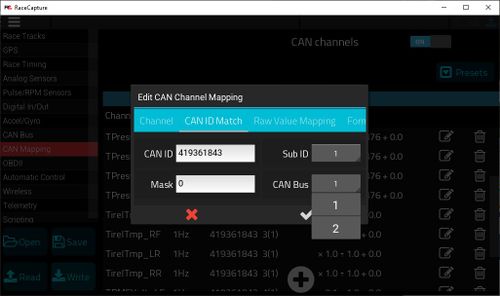
NOTE: If you wire a device to CAN bus 2, you will probably have to go into each channel and change it from CAN Bus 1 to CAN Bus 2.