RGB-bolt-on
Introduction
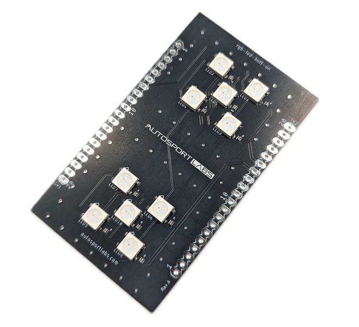
The RGB LED Bolt-on for the ESP32-X2 development board features WS2812B LEDs, offering advanced, customizable lighting capabilities. Each LED integrates red, green, and blue diodes with a built-in driver IC, enabling individual control over colors and effects. The WS2812B's "smart" functionality allows for complex lighting effects, like color transitions and animations, without extensive wiring.
Key Features
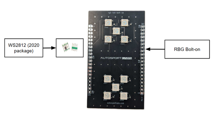
- 10 WS2812B LEDs are arranged in two groups of 5, offering flexibility in lighting configurations for projects requiring dynamic visual feedback.
- The LED Bolt-On is ideal for enhancing user experience with interactive lighting effects for applications like status indication, visual debugging, and creative lighting displays.
Application
LED bolt-on consists of regular-sized and versatile LEDs making it possible to use in a variety of applications some of the applications of the button bolt-on include the following:
- Visual Feedback for CAN Messages: Indicates message transmission, reception, or error states with dynamic color changes.
- Creative Lighting Displays: Create interactive and animated lighting effects for entertainment or aesthetic applications.
- Status Indicators: Display system health, warnings, or operating modes using unique LED patterns.
- Debugging Tool: Use LEDs as real-time visual indicators for system states during some technical fault.
Getting Started
The following components are included in the assembled PCB board for LED bolt-on
- 10x WS2812B LEDs (5050 packages) pre-assembled on a high-quality PCB.
- Bolt-on board dimensions tailored for the ESP32-CAN-X2 module.
The following components need to be soldered with assembled LED bolt-on
- 2 x 20-pin headers for connection to the ESP32-CAN-X2 module. These headers are available separately from a variety of sources (male/female) Amazon | Ebay
- Compatible 5V power supply (if testing standalone).
Assembly Instructions
- Align the LED Bolt-On board with the ESP32-CAN-X2, ensuring proper orientation by matching the WiFi antenna and USB icons.
- Solder the 20-pin headers onto the bolt-on board for secure connections.
- Plug the bolt-on board onto the ESP32-CAN-X2.
Hardware Connections
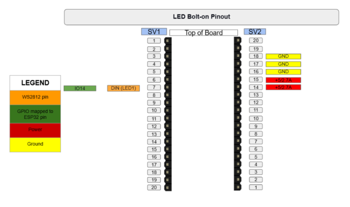
The DIN pin of the first LED is connected to GPIO14 (Pin 7 on the SV1 header) of the ESP32. Following is the pinout of the RGB LED bolt-on

- The data is transmitted sequentially through the LEDs, with the DOUT pin of one LED connected to the DIN pin of the next. Below is the pinout of the WS2812B LED used in the bolt-on.
| No. | Symbol | Description |
|---|---|---|
| 1 | VDD | Power Supply: Connect to a 5V DC power source to power the LED. Ensure stable voltage for optimal performance. |
| 2 | DOUT | Data Signal Output: Outputs the control data signal to the next LED in the chain, enabling sequential data transmission across multiple LEDs. Connect to the DIN of the following LED if chaining. |
| 3 | VSS | Ground: Connect to the ground (0V) of the power supply. This pin must be connected to the ground of the controller for proper operation. |
| 4 | DIN | Data Signal Input: Receives the control data signal from the microcontroller or the previous LED in the chain. This input allows each LED to be individually controlled. |
Project Examples
Project 1: Visual CAN Message Indicator
Description: Use the LEDs to indicate message states (e.g., green for sent, red for error). Steps:
- Connect the RGB LED bolt-on on top of the ESP32-CAN-X2 board through SV1 and SV2 in the correct configuration.
- Program the ESP32-CAN-X2 to send specific CAN messages and display corresponding LED colors.
- Create animations to indicate message priority or status.
Project 2: System Health Dashboard
Description: Display system health using LED colors (e.g., green for normal, yellow for warnings, red for critical states). Steps:
- Connect the RGB LED bolt-on on top of the ESP32-CAN-X2 board through SV1 and SV2 in the correct configuration.
- Map system parameters to specific LED groups and program the ESP32-CAN-X2 board
- Update LED states dynamically based on incoming data.
Project 3: Interactive Lighting Display
Description: Use the LEDs to create creative patterns or animations triggered by button presses or external inputs. Steps:
- Connect the RGB LED bolt-on on top of the ESP32-CAN-X2 board through SV1 and SV2 in the correct configuration.
- Program ESP32-CAN-X2 board with unique lighting effects using libraries like Adafruit NeoPixel.
- Synchronize animations with button inputs or other sensors.
Demo Code
Example code for controlling the WS2812B LEDs will be available in the official repository. The demo will include:
- Basic control of LED colors.
- Animated lighting patterns.


