Sequential shift light
Summary
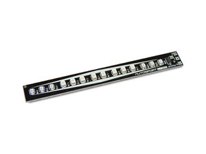
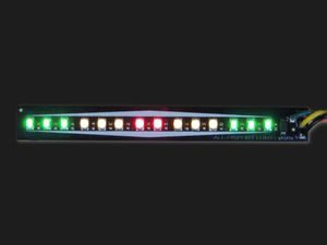
The Sequential Shift Light is a compact 4.2" x 0.5" display made up of 14 LEDs in a 3 stage array.
LED configuration
- 6 green LEDs comprise the outer segments, wired together
- 6 yellow LEDs comprise the middle segments, wired together
- 2 red LEDs are in the center, wired together
Physical Features
- All surface mount construction for ruggedness and a smooth bottom, ideal for mounting with double stick foam tape.
Electrical Connections
- +5v common power
- 3 triggers to activate each color segment
Wiring
RaceCapture/Pro
Hardware Configuration
- MK1 only Ensure all 3 internal Digital Input/Output jumpers on the RaceCapture/Pro board are set to output mode. Refer to the Installation Guide for details.
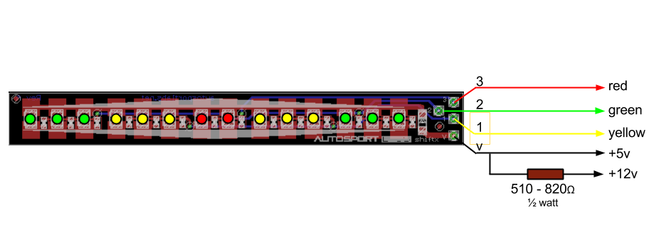
- Connect the Green, Yellow and Red connections from the Sequential Shift light board to Digital Input/Output 1,2,3 respectively.
- Connect the V connection to either:
- The +5v voltage reference
- A separate 5V power supply
- 12v with an extra current limiting resistor you supply. (See Diagram)
Software Configuration
- Launch the RaceCapture App
- Connect RaceCapture/Pro to your computer.
- Read the current configuration from RaceCapture/Pro.
- On the Digital Input/Output configuration page set the GPIO ports to output mode.
- Write the configuration back to RaceCapture/Pro.
- Power cycle RCP for changes to take effect
Lua Script
The Lua Script defines the logic for reading the sensor inputs and controlling the various outputs.
- In RaceAnalyzer, navigate to the scripting window
- Paste the following code into the window
- Change the 5000, 6000 and 7000 values to the shift light threshold you prefer.
- Press 'write script' to write the script back to RaceCapture/Pro
- Power-cycle (unplug/replug) RaceCapture/Pro to activate the script.
setTickRate(15)

function onTick()
	local r = getTimerRpm(0)
	if r > 5000 then setGpio(2,1) else setGpio(2,0) end
	if r > 6000 then setGpio(1,1) else setGpio(1,0) end
	if r > 7000 then setGpio(0,1) else setGpio(0,0) end
end
- Tip - you can perform the setup on the bench just using USB power.
Megajolt
These instructions apply to all versions of the Megajolt system.
Hardware connections
- Connect the Sequential Shift Light board as follows:
- Green to PGM3
- Yellow to PGM4
- Red to Shift Light output
- Voltage supply (V) to either
- The +5v voltage reference output
- A separate 5V power supply
- 12v with an extra current limiting resistor you supply. (See Diagram)
Software Configuration
- Launch the Megajolt Configuration Software and read the configuration from the controller
- In the user output screen, set the indicator points you want for the Green, Yellow and Red connections.
- Write the configuration back to the Megajolt controller.


