Trigger Wheel Designs
Crank Pulley Strategies
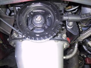
Adapting Trigger Wheel to Existing Crank Pulley
The most common approach is to mate a pre-made Trigger Wheel to the existing OEM crank pulley. Often the trigger wheel must be mounted on the outboard portion of the crank pulley as there is usually not enough room between the crank pulley and block.
Toyota 4AG Trigger wheel installation
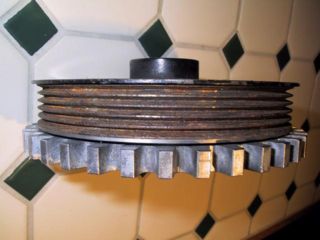
Machining Pattern into Crank Pulley
If the crank pulley has extra material to machine the necessary 36-1 pattern, identical results can be obtained compared to the 'traditional' technique of mating special trigger wheels to crank pulleys.
The technique used can be as elaborate as replicating the equivalent trigger wheel teeth pattern into the pulley, to simply milling/drilling a series of holes representing the pattern. Regardless of technique used, it's critical the pattern is accurately machined into the pulley to ensure proper ignition timing.
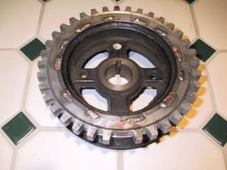
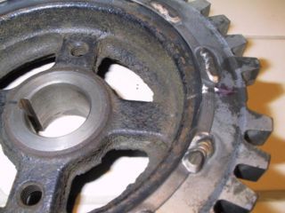
The following image is an aftermarket VW pulley, modified with the 36-1 pattern using round holes realize the trigger wheel pattern.
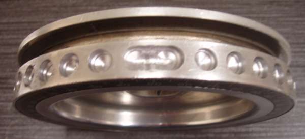
courtesy of Alexander_Monday
The following pulley has it's face modified with the required 36-1 pattern. A clever sensor bracket design will be required for this installation.
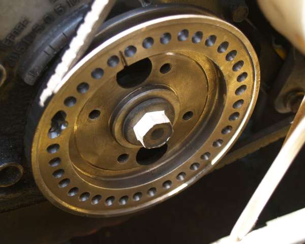
courtesy of pope101
Sensor Bracket Design
Sensor brackets must be designed to be extremely rigid to maintain proper alignment and clearance under all operating conditions. A weak bracket design will vibrate during engine operation- especially at certain RPM ranges.
Symptoms of Poor Bracket Design
- Strikes/rubbing on trigger wheel and sensor
- Sensor is making contact against trigger wheel during engine operation
- Engine misfiring / hesitation during certain RPM ranges
- Sensor is vibrating excessively- affecting the VR Signal supplied to the Ignition System. The system can handle signal variances up to a certain point; beyond this point the system loses 'sync' with the trigger wheel, causing the mis-firing.
Without access to sophisticated tools for mechanical design and simulation, most will take the pragmatic approach and 'over design' the bracket for strength and rigidity.
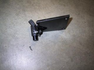
Example Bracket Design
Note the bracket thickness of in relation to the size.
Per Vehicle Installations
Be sure to see our Forums for the latest designs contributed by the community
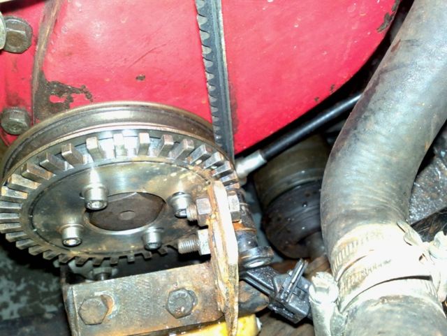
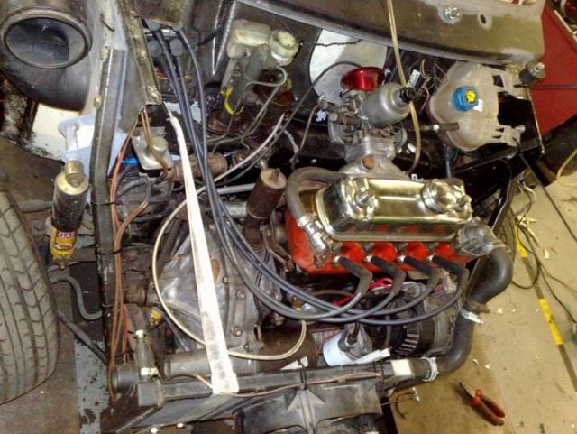
1275 A-Series Austin Mini
- Courtesy of NITROPIXIE
- Year: 1989
- Trigger Wheel Source: Made at local engineering shop for £70. Teeth are 10mm deep as VR sensor is located at 90 degs to wheel. Used a 998 pulley without damper. Rivets ground out and holes threaded. Triggerwheel is mounted with 4 bolts. 10 deg adjustment in triggerwheel. Triggerwheel diameter equals the pully diameter.
- VR Sensor Source: Ford Ka
- VR Location/mounting bracket: Radiator now mounted at the front and used the old radiator mount bracket to form a bracket to now hold the VR sensor as in picture. Strap holds Vr sensor. Vr sensor can only be adjusted in distance from wheel.

