AnalogX2: Difference between revisions
| (33 intermediate revisions by the same user not shown) | |||
| Line 13: | Line 13: | ||
==Harness / Cabling== | ==Harness / Cabling== | ||
AnalogX is designed for plug and play connection into Autosport Labs CAN bus networks and sensors. Parts and cables shown are available individually. Refer to the part numbers below to create your own sensor configuration. | |||
AnalogX is designed for plug and play connection into Autosport Labs CAN bus networks and sensors. Refer to the part numbers below to create your own sensor configuration. | |||
====CAN bus connection to RaceCapture==== | |||
[[image:analogX_CAN_connection.jpg]] | [[image:analogX_CAN_connection.jpg]] | ||
{| class="wikitable" | |||
|- | |||
! SKU !! Description | |||
|- | |||
| ASL_DUAL_CAN_HUB || Powered, 8 port dual CAN bus hub kit | |||
|- | |||
| ASL_M8_CAN_EXT_0.5M<br/>ASL_M8_CAN_EXT_1M<br/>ASL_M8_CAN_EXT_2M<br/>ASL_M8_CAN_EXT_3M<br/>ASL_M8_CAN_EXT_4M || CAN extension cable, M8 4P female to M8 4P male, 0.5 - 4 Meter lengths | |||
|} | |||
====Sensor Connections==== | |||
[[image:analogX_plug_and_play_sensors.jpg]] | [[image:analogX_plug_and_play_sensors.jpg]] | ||
{| class="wikitable" | {| class="wikitable" | ||
| Line 39: | Line 48: | ||
===Bare pigtails=== | ===Bare pigtails=== | ||
For a custom or non-plug and play | For a custom or non-plug and play installation, these bare pigtail cables are available for connecting AnalogX: | ||
{| class="wikitable" | {| class="wikitable" | ||
|- | |- | ||
| Line 48: | Line 57: | ||
| ASL_M8_QUAD_SENSOR_PIGTAIL_2M || M8 8P male to bare wire quad sensor pigtail, 1M, 24AWG | | ASL_M8_QUAD_SENSOR_PIGTAIL_2M || M8 8P male to bare wire quad sensor pigtail, 1M, 24AWG | ||
|} | |} | ||
See the [[AnalogX2#Wiring|Wiring]] guide for pinout information. | |||
==Compatible Sensors== | ==Compatible Sensors== | ||
| Line 59: | Line 69: | ||
This will bring in the basic mapping with the default 0-5v scaling. From here, you can edit each channel to customize the formula to match your sensor's voltage scaling. | This will bring in the basic mapping with the default 0-5v scaling. From here, you can edit each channel to customize the formula to match your sensor's voltage scaling. | ||
* '''Note''' - RaceCapture's CAN mapping features currently only supports sensors with a linear (straight-line) response. Sensors with a curved response, such as the Extended Range Temperature sensor is based on a thermistor design, and will not work with the built-in direct CAN mapping. We recommend using a temperature sensor with a linear response, such as the Texense Liquid Temperature Sensor or similar. | * '''Note''' - RaceCapture's CAN mapping features currently only supports sensors with a linear (straight-line) response. Sensors with a curved response, such as the Extended Range Temperature sensor is based on a thermistor design, and will not work with the built-in direct CAN mapping. We recommend using a temperature sensor with a linear response, such as the Autosport Labs Linear Temperature Sensor, Texense Liquid Temperature Sensor or similar. | ||
===Setting CAN baud rate=== | ===Setting CAN baud rate=== | ||
| Line 67: | Line 77: | ||
Select the starter CAN preset for AnalogX. This will bring in the basic 0-5v mapping, which you can then calibrate further using the CAN mapping conversion formula. | Select the starter CAN preset for AnalogX. This will bring in the basic 0-5v mapping, which you can then calibrate further using the CAN mapping conversion formula. | ||
[[file: | [[file:analogx2_preset_app.jpg|640px]] | ||
===Calibrating Sensors attached to AnalogX=== | ===Calibrating Sensors attached to AnalogX=== | ||
| Line 75: | Line 85: | ||
Touch the channel selection drop down and select the channel that matches your sensor. | Touch the channel selection drop down and select the channel that matches your sensor. | ||
* '''Note, it's recommended you use the preset name for your channels; if no channel exists that matches your sensor, you can customize the channel name, units, and min/max values directly | * '''Note, it's recommended you use the preset name for your channels; if no channel exists that matches your sensor, you can customize the channel name, units, and min/max values directly | ||
==Sensor Conversion Formulas== | ==Sensor Conversion Formulas== | ||
| Line 101: | Line 109: | ||
for 0-150 PSI use the formula: '''RAW * 0.0375 - 18.75''' | for 0-150 PSI use the formula: '''RAW * 0.0375 - 18.75''' | ||
* '''Note:''': The 0. | * '''Note:''': The 0.0375 value was derived from the formua: 150 PSI / 4000mV = 0.0375 PSI/mV | ||
[[file:AnalogX_150PSI_oil_pressure_example_formula.png|480px]] | [[file:AnalogX_150PSI_oil_pressure_example_formula.png|480px]] | ||
| Line 137: | Line 145: | ||
===Other sensors=== | ===Other sensors=== | ||
Please refer to these manufacturer's user guide on how to map data using the provided AnalogX CAN protocol. | Please refer to these manufacturer's user guide on how to map data using the provided AnalogX CAN protocol. | ||
==Wiring== | |||
===Power and CAN=== | |||
* Connector: M8 4P Male, A coding | |||
[[file:M8_4P_male_pinout.jpg|200px]] | |||
{| class="wikitable" | |||
|- | |||
! Pin !! Connection !! Notes | |||
|- | |||
| 1 || CAN low || | |||
|- | |||
| 2 || Power || Red, 12-14v / 50mA | |||
|- | |||
| 3 || CAN high || | |||
|- | |||
| 4 || Ground || Black | |||
|} | |||
Power is standard automotive 12-14v (nominal). | |||
===Sensor connections=== | |||
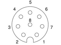
* Connector: M8 8P Female, A coding | |||
[[file:M8_8P_female_pinout.jpg|200px]] | |||
{| class="wikitable" | |||
|- | |||
! Pin !! Connection !! Notes | |||
|- | |||
| 1 || Analog/Digital 1 || | |||
|- | |||
| 2 || Analog/Digital 2 || | |||
|- | |||
| 3 || Analog/Digital 4 || | |||
|- | |||
| 4 || Vref || 5v @ 1A max current, combined with pin 6 | |||
|- | |||
| 5 || Ground || | |||
|- | |||
| 6 || Vref || 5v @ 1A max current, combined with pin 4 | |||
|- | |||
| 7 || Analog/Digital 3 || | |||
|- | |||
| 8 || Ground || | |||
|} | |||
* '''Note''': The AnalogX inputs are very high impedance, allowing connection to existing circuits / sensors without affecting the reading of that circuit. As such, no pull-up or pull-down resistors are provided and must be added externally if needed. | |||
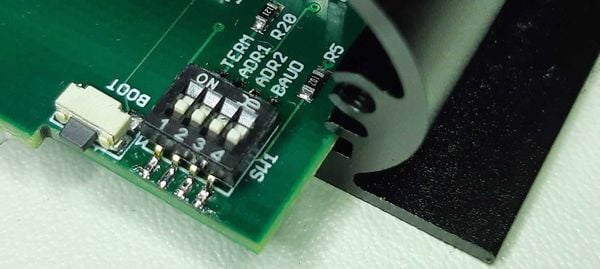
==DIP switch settings== | |||
You can access the DIP switches by removing the end plate on the CAN + power side. These switches enable an number of options: | |||
{| class="wikitable" | |||
|- | |||
! Switch !! Function || Description | |||
|- | |||
| 1 || Termination || Set to ON to enable CAN termination | |||
|- | |||
| 2 || Address offset 1 || [[AnalogX2#Adjusting_Base_ID|Used to select the base CAN address]] | |||
|- | |||
| 3 || Address offset 2 || [[AnalogX2#Adjusting_Base_ID|Used to select the base CAN address]] | |||
|- | |||
| 4 || CAN Baud Rate || OFF to enable 1M (default), ON to enable 500K | |||
|} | |||
[[image: analogx2_dip_switch.jpg|600px]] | |||
===CAN termination=== | |||
AnalogX is not terminated by default. You can enable termination by switching the [[AnalogX2#DIP_switch_settings|termination DIP switch]] to ON. | |||
==Installation== | |||
You can mount AnalogX2 to any flat mounting service. For best performance and reliability, keep away from sources of heat. | |||
==Troubleshooting== | ==Troubleshooting== | ||
===No CAN data=== | ===No CAN data=== | ||
* Ensure AnalogX is receiving 12v via it's connection. | |||
** '''Note''': Ensure your data system is also receiving 12v if it is powering AnalogX | |||
* Double check the CAN bus connections | * Double check the CAN bus connections | ||
* Verify the CAN baud rate is compatible with the AnalogX configuration (1M by default, 500K enabled with DIP switch) | * Verify the CAN baud rate is compatible with the AnalogX configuration (1M by default, 500K enabled with DIP switch) | ||
| Line 188: | Line 268: | ||
| Input voltage protection | | Input voltage protection | ||
| 100v | | 100v | ||
|- | |||
| CAN baud rate | |||
| 1M and 500K, jumper configurable | |||
|- | |||
| Address Space | |||
| 4 separate address spaces allows up to 4 AnalogX modules to operate on the same CAN network. (DIP switch configurable) | |||
|- | |- | ||
| Power input and connections | | Power input and connections | ||
| Line 196: | Line 282: | ||
|- | |- | ||
| Weight | | Weight | ||
| | | 100gm (approximately) | ||
|- | |- | ||
| Dimensions | | Dimensions | ||
| 60 x 60 (approximately) | | 60 x 60 (approximately) | ||
|- | |- | ||
| | | Environmental | ||
| | | IP65, 0-85C | ||
|} | |} | ||
=AnalogX CAN bus API= | =AnalogX CAN bus API= | ||
| Line 275: | Line 300: | ||
====Adjusting Base ID==== | ====Adjusting Base ID==== | ||
The base address is determined by the state of the '''ADR1''' and '''ADR2''' | The base address is determined by the state of the '''ADR1''' and '''ADR2''' [[AnalogX2#DIP_switch_settings|DIP switches]], accessible behind the power + CAN end plate. By default, the DIP switches are off. | ||
* | * Switching on ADR1 will add 256 to the base ID | ||
* | * Switching on ADR2 will add 512 to the base ID. | ||
The combination of jumper settings will allow up to 4 AnalogX units to coexist on the same CAN bus. | The combination of jumper settings will allow up to 4 AnalogX units to coexist on the same CAN bus. | ||
| Line 284: | Line 309: | ||
{| class="wikitable" | width="600px" | {| class="wikitable" | width="600px" | ||
|- | |- | ||
! ADR2 | ! ADR2 switch | ||
! ADR1 | ! ADR1 switch | ||
! Address | ! Address | ||
|- | |- | ||
| | | Off | ||
| | | Off | ||
| 0xE4600 (935424) | | 0xE4600 (935424) | ||
|- | |- | ||
| | | Off | ||
| | | On | ||
| 0xE4700 (935680) | | 0xE4700 (935680) | ||
|- | |- | ||
| | | On | ||
| | | Off | ||
| 0xE4800 (935936) | | 0xE4800 (935936) | ||
|- | |- | ||
| | | On | ||
| | | On | ||
| 0xE4900 (936192) | | 0xE4900 (936192) | ||
|} | |} | ||
| Line 307: | Line 332: | ||
===CAN Baud rate=== | ===CAN Baud rate=== | ||
500K | 1M and 500K rates are supported | ||
1M is enabled by default; switch on the '''Baud''' [[AnalogX2#DIP_switch_settings|DIP switch]] to enable 500K data rate. | |||
==CAN Messages== | ==CAN Messages== | ||
| Line 318: | Line 343: | ||
====Address==== | ====Address==== | ||
'''CAN ID:''' Base + 0 | '''CAN ID:''' Base + 0x0 (0) | ||
{| class="wikitable" | width="600px" | {| class="wikitable" | width="600px" | ||
| Line 331: | Line 356: | ||
|- | |- | ||
| 1 | | 1 | ||
| | | Current sample rate, in Hz | ||
| | | | ||
|- | |- | ||
| Line 363: | Line 388: | ||
Configures options for AnalogX. | Configures options for AnalogX. | ||
Send this message to AnalogX to configure runtime settings. | Send this message to AnalogX to configure runtime settings. Settings are saved in flash memory and will be preserved across power cycles. | ||
* '''Note:''' | * '''Note:''' To read the current settings, broadcast a message with this CAN ID with no data (data length of 0) - AnalogX will reply with the current configuration. | ||
====Address==== | ====Address==== | ||
'''CAN ID:''' Base + 3 | '''CAN ID:''' Base + 0x3 (3) | ||
{| class="wikitable" | width="600px" | {| class="wikitable" | width="600px" | ||
| Line 414: | Line 439: | ||
====Address==== | ====Address==== | ||
'''CAN ID:''' Base + 2 | '''CAN ID:''' Base + 0x2 (2) | ||
{| class="wikitable" | width="600px" | {| class="wikitable" | width="600px" | ||
| Line 464: | Line 489: | ||
===Address=== | ===Address=== | ||
* '''CAN ID:''' Base + 20 | * '''CAN ID:''' Base + 0x14 (20) | ||
{| class="wikitable" | width="600px" | {| class="wikitable" | width="600px" | ||
Latest revision as of 16:12, 17 September 2024
Introduction
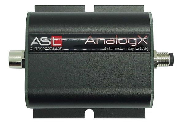
AnalogX is a compact 4 channel Analog to CAN I/O expander, specially designed for the harsh automotive electrical environment.
AnalogX provides 4 buffered and protected 0-5v sensor inputs and can broadcast the sensor values between 1 and 255Hz. It also provides a 0.5A 5v reference for powering sensors.
Parts in the Kit
In the kit you will receive:
- AnalogX2 module
- Note Cabling is available separately, depending on how you design your sensor layout.
Harness / Cabling
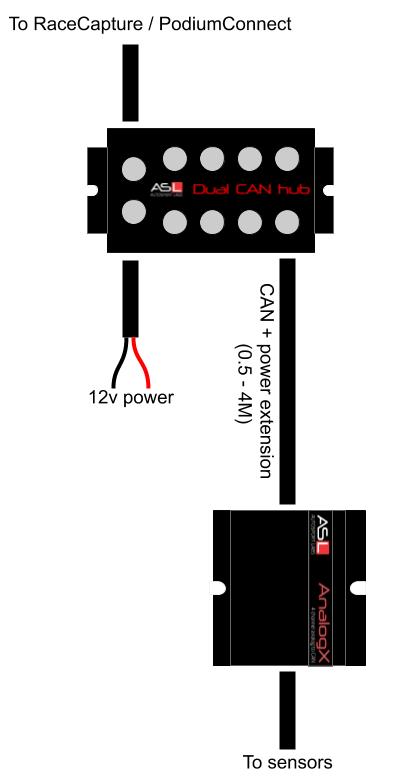
AnalogX is designed for plug and play connection into Autosport Labs CAN bus networks and sensors. Parts and cables shown are available individually. Refer to the part numbers below to create your own sensor configuration.
CAN bus connection to RaceCapture
| SKU | Description |
|---|---|
| ASL_DUAL_CAN_HUB | Powered, 8 port dual CAN bus hub kit |
| ASL_M8_CAN_EXT_0.5M ASL_M8_CAN_EXT_1M ASL_M8_CAN_EXT_2M ASL_M8_CAN_EXT_3M ASL_M8_CAN_EXT_4M |
CAN extension cable, M8 4P female to M8 4P male, 0.5 - 4 Meter lengths |
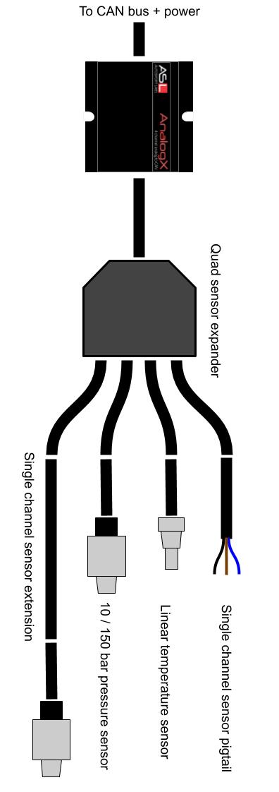
Sensor Connections
| SKU | Description |
|---|---|
| ASL_4X_SENSOR_SPLITTER | 4X sensor expander |
| ASL_M8_SENSOR_EXTENSION_1M ASL_M8_SENSOR_EXTENSION_2M ASL_M8_SENSOR_EXTENSION_3M ASL_M8_SENSOR_EXTENSION_4M |
Single channel sensor extension cable |
| ASL_LINEAR_TEMP_M8 | Linear temperature sensor |
| ASL_10_BAR_DELPHI3_M8 | 10 bar (150 PSI) pressure sensor |
| ASL_150_BAR_DELPHI3_M8 | 150 bar (2175 PSI) pressure sensor |
| ASL_M8_SENSOR_PIGTAIL_2M | Single sensor pigtail for custom sensor connection, 2 Meters |
Bare pigtails
For a custom or non-plug and play installation, these bare pigtail cables are available for connecting AnalogX:
| SKU | Description |
|---|---|
| ASL_DEVICE_CAN_PIGTAIL_1M | CAN + power pigtail for connecting device, M8 4P male to bare wires, 1 meter |
| ASL_M8_QUAD_SENSOR_PIGTAIL_2M | M8 8P male to bare wire quad sensor pigtail, 1M, 24AWG |
See the Wiring guide for pinout information.
Compatible Sensors
AnalogX is compatible with any 0-5v voltage input; the voltage is broadcast over CAN bus with the value range of 0 - 5000mV.
Use the capabilities provided by the receiving data system to translate the raw voltage to a meaningful real-world value, such as pressure, temperature, distance, and so on.
RaceCapture / PodiumConnect systems
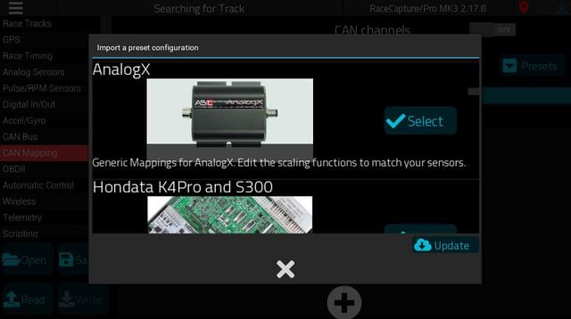
Setting up AnalogX in RaceCapture is easy: Go to Setup / CAN Channels and select the preset for AnalogX.
This will bring in the basic mapping with the default 0-5v scaling. From here, you can edit each channel to customize the formula to match your sensor's voltage scaling.
- Note - RaceCapture's CAN mapping features currently only supports sensors with a linear (straight-line) response. Sensors with a curved response, such as the Extended Range Temperature sensor is based on a thermistor design, and will not work with the built-in direct CAN mapping. We recommend using a temperature sensor with a linear response, such as the Autosport Labs Linear Temperature Sensor, Texense Liquid Temperature Sensor or similar.
Setting CAN baud rate
The default baud rate for AnalogX is 1M. Ensure this matches the setting under Setup / CAN bus settings.
Selecting the AnalogX preset
Select the starter CAN preset for AnalogX. This will bring in the basic 0-5v mapping, which you can then calibrate further using the CAN mapping conversion formula.
Calibrating Sensors attached to AnalogX
Navigate to Setup / CAN mapping, and edit the channel you wish to customize.
Select the channel
Touch the channel selection drop down and select the channel that matches your sensor.
- Note, it's recommended you use the preset name for your channels; if no channel exists that matches your sensor, you can customize the channel name, units, and min/max values directly
Sensor Conversion Formulas
AnalogX reports it's raw value from 0-5000mV. You can use the formula to scale and offset the raw value to a real-world value.
Linear Fluid Temperature Sensor
The Autosport Labs Linear Fluid Temperature (ASL_LINEAR_TEMP_M8) sensor has a 10mV/C scaling, with a 0.5V offset at 0C.
10 bar / 150 PSI pressure sensor
The Autosport Labs 10 bar pressure sensor (ASL_10_BAR_DELPHI3_M8) has the following calibration / range:
(0 - 10 bar / 150 PSI range)
- 0.5v 0 bar / = 0 PSI
- 4.5v = 10 bar / 150 PSI
The sensor has a 4000mV range between min and max values, with a 500mV offset.
Therefore,
The offset is calculated based on the 500mV offset of the sensor (500mv * 0.375 = 18.75)
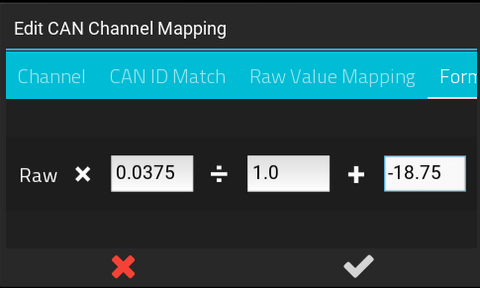
for 0-150 PSI use the formula: RAW * 0.0375 - 18.75
- Note:: The 0.0375 value was derived from the formua: 150 PSI / 4000mV = 0.0375 PSI/mV
150 Bar / 2175 PSI pressure sensor
The Autosport Labs 150 bar pressure sensor (ASL_150_BAR_DELPHI3_M8) has the following calibration / range:
(0 - 150 bar / 2175 PSI range)
- 0.5v = 0 bar / 0 PSI
- 4.5v = 150 bar / 2175 PSI
for 0-2175 PSI, use the formula: RAW * 0.5437 - 271.85
Texense Liquid Temperature Sensor
This sensor has a range of -50 to 150C and has a 22.5mV/C calibration.
0.25v = -50C 4.75v = 150C (200C sweep)
The sensor has a 4500mV range between -50C and 150C, with a 250mV offset.
Therefore, 200C / 4500mV = 0.04444 C/mV
The offset is calculated based on the 250mV offset of the sensor (250mV * 0.0444444 = 11.1111)
The offset is further adjusted by the starting range of the sensor (-50C)
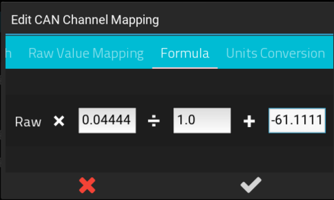
Resulting formula: RAW * 0.04444 - 61.1111
- Note you can convert the resulting value to Fahrenheit by selecting the C -> F option in the Formula Conversions Tab.
Other sensors
Please refer to these manufacturer's user guide on how to map data using the provided AnalogX CAN protocol.
Wiring
Power and CAN
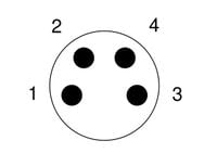
- Connector: M8 4P Male, A coding
| Pin | Connection | Notes |
|---|---|---|
| 1 | CAN low | |
| 2 | Power | Red, 12-14v / 50mA |
| 3 | CAN high | |
| 4 | Ground | Black |
Power is standard automotive 12-14v (nominal).
Sensor connections
- Connector: M8 8P Female, A coding
| Pin | Connection | Notes |
|---|---|---|
| 1 | Analog/Digital 1 | |
| 2 | Analog/Digital 2 | |
| 3 | Analog/Digital 4 | |
| 4 | Vref | 5v @ 1A max current, combined with pin 6 |
| 5 | Ground | |
| 6 | Vref | 5v @ 1A max current, combined with pin 4 |
| 7 | Analog/Digital 3 | |
| 8 | Ground |
- Note: The AnalogX inputs are very high impedance, allowing connection to existing circuits / sensors without affecting the reading of that circuit. As such, no pull-up or pull-down resistors are provided and must be added externally if needed.
DIP switch settings
You can access the DIP switches by removing the end plate on the CAN + power side. These switches enable an number of options:
| Switch | Function | Description |
|---|---|---|
| 1 | Termination | Set to ON to enable CAN termination |
| 2 | Address offset 1 | Used to select the base CAN address |
| 3 | Address offset 2 | Used to select the base CAN address |
| 4 | CAN Baud Rate | OFF to enable 1M (default), ON to enable 500K |
CAN termination
AnalogX is not terminated by default. You can enable termination by switching the termination DIP switch to ON.
Installation
You can mount AnalogX2 to any flat mounting service. For best performance and reliability, keep away from sources of heat.
Troubleshooting
No CAN data
- Ensure AnalogX is receiving 12v via it's connection.
- Note: Ensure your data system is also receiving 12v if it is powering AnalogX
- Double check the CAN bus connections
- Verify the CAN baud rate is compatible with the AnalogX configuration (1M by default, 500K enabled with DIP switch)
- Verify your CAN bus termination is correct. (Not terminated by default, enabled with DIP switch)
- Simplify your CAN bus network: Try making AnalogX the only other CAN device on the network, just as a test.
- Check for short circuits / over-current on the 5v reference. If too much current is drawn from the 5v reference, AnalogX may shut down in self-protection mode.
Data is being received, but it is incorrect
Basic mapping test
Try simplifying the mapping to verify the correct data is transmitted.
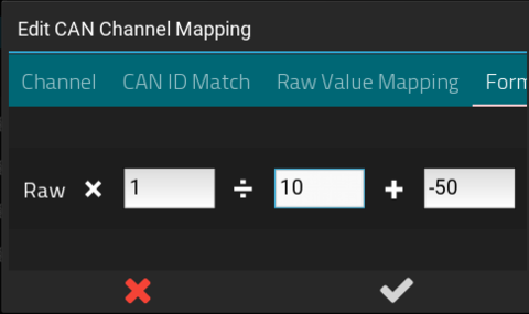
- Go into the software for the receiving system, and set the CAN formula to multiply by 1 and add 0 and divide by 1 , and unsigned integer. and update the software settings.
- This will cause the receiving system to display the raw millivolt (mV) value from AnalogX.
- Disconnect the sensors from AnalogX.
- For each AnalogX input perform the following test:
- Connect the input to AnalogX's ground. Your receiving system should show very close to 0, which is 0 volts.
- Connect the input to AnalogX's 5v reference. Your receiving system should show very close to 5000, which represents 5000mV.
- Note: The AnalogX inputs are very sensitive and high impedance to prevent affecting the readings of existing circuits. Therefore, if the inputs are disconnected, it will 'float' and may show random readings.
If you can confirm these readings, then perform the additional steps:
- For each AnalogX input, re-connect your sensor.
- Measure the voltage right where it enters AnalogX.
- Compare that with the reading on the receiving system. The value should be the voltage X 1000, translated to mV. Example: 2.5v measured should show 2500 on the receiving system.
If you can verify received millivolt value equals the measured voltage at the AnalogX input, then you know the correct value is being transmitted to the system, and you can focus on mapping the raw millivolt value to the real world temperature, pressure, or etc. Consult the sensor manufacturer and the system to determine the proper mapping of the sensor you are using.
Specifications
| Feature | Description |
|---|---|
| Analog sensor input voltage range | 0 - 5v |
| DAC resolution | 12 bit SAR |
| Sample output format | 0 - 5000mV |
| Input impedance | Greater than 10 Meg Ohm |
| Input voltage protection | 100v |
| CAN baud rate | 1M and 500K, jumper configurable |
| Address Space | 4 separate address spaces allows up to 4 AnalogX modules to operate on the same CAN network. (DIP switch configurable) |
| Power input and connections | 9 - 15volts, protected to 40v (intermittent) |
| Harness | M8 4P Male for power + ground, M8 8P for sensor connection |
| Weight | 100gm (approximately) |
| Dimensions | 60 x 60 (approximately) |
| Environmental | IP65, 0-85C |
AnalogX CAN bus API
Overview
The CAN bus API provides the configuration and control interface for AnalogX
CAN base ID
CAN base ID is 0xE4600 (935424)
Adjusting Base ID
The base address is determined by the state of the ADR1 and ADR2 DIP switches, accessible behind the power + CAN end plate. By default, the DIP switches are off.
- Switching on ADR1 will add 256 to the base ID
- Switching on ADR2 will add 512 to the base ID.
The combination of jumper settings will allow up to 4 AnalogX units to coexist on the same CAN bus.
| ADR2 switch | ADR1 switch | Address |
|---|---|---|
| Off | Off | 0xE4600 (935424) |
| Off | On | 0xE4700 (935680) |
| On | Off | 0xE4800 (935936) |
| On | On | 0xE4900 (936192) |
CAN Baud rate
1M and 500K rates are supported
1M is enabled by default; switch on the Baud DIP switch to enable 500K data rate.
CAN Messages
Announcement
The announcement message is broadcast by the AnalogX upon power up.
Address
CAN ID: Base + 0x0 (0)
| Offset | What | Value |
|---|---|---|
| 0 | Channel Count | Total number of channels on device |
| 1 | Current sample rate, in Hz | |
| 2 | Reserved | |
| 3 | Reserved | |
| 4 | Reserved | |
| 5 | Major Version | Firmware Major Version Number |
| 6 | Minor Version | Firmware Minor Version Number |
| 7 | Patch Version | Firmware Patch version number |
Configuration Group 1
Configures options for AnalogX.
Send this message to AnalogX to configure runtime settings. Settings are saved in flash memory and will be preserved across power cycles.
- Note: To read the current settings, broadcast a message with this CAN ID with no data (data length of 0) - AnalogX will reply with the current configuration.
Address
CAN ID: Base + 0x3 (3)
| Offset | What | Value |
|---|---|---|
| 0 | Sample Rate | Rate to report sensor values ( 1 - 255Hz). Default sample rate is 50Hz. |
| 1 | Reserved | |
| 2 | Reserved | |
| 3 | Reserved | |
| 4 | Reserved | |
| 5 | Reserved | |
| 6 | Reserved | |
| 7 | Reserved |
Statistics
Broadcast by AnalogX every 1 second.
Address
CAN ID: Base + 0x2 (2)
| Offset | What | Value |
|---|---|---|
| 0 | Current Sample Rate | 1 - 255Hz |
| 1 | Reserved | |
| 2 | Reserved | |
| 3 | Reserved | |
| 4 | Reserved | |
| 5 | Major Version | Firmware Major Version Number |
| 6 | Minor Version | Firmware Minor Version Number |
| 7 | Patch Version | Firmware Patch version number |
Sample Broadcast
Sample Broadcast for Analog inputs. The samples are broadcast based on the configured sample rate (default is 50Hz)
Scaling and Data format
- Scaling: 0-5000mV
- Data format: Little Endian
Address
- CAN ID: Base + 0x14 (20)
| Offset | What | Value |
|---|---|---|
| 0 | Channel 1, low byte | |
| 1 | Channel 1, high byte | |
| 2 | Channel 2, low byte | |
| 3 | Channel 2, high byte | |
| 4 | Channel 3, low byte | |
| 5 | Channel 3, high byte | |
| 6 | Channel 4, low byte | |
| 7 | Channel 4, high byte |

