ESP32-CAN-X2/RevC: Difference between revisions
(Created page with "=6 pin JST-PH Connector= The ESP32-CAN-X2 REV C development board provides an additional 6-pin connector header at the top of the board to support CAN communication. This header makes wiring the device more convenient and robust. The CAN communication connection pinout details are given in the pinout section below. Top Header Pinout The header supports CAN communication. Pin count starts at the left viewing the board from the top. The pinout configuration of the header...") |
|||
| Line 3: | Line 3: | ||
Top Header Pinout | Top Header Pinout | ||
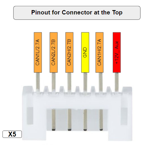
The header supports CAN communication. Pin count starts at the left viewing the board from the top. The pinout configuration of the header is shown in | The header supports CAN communication. Pin count starts at the left viewing the board from the top. The pinout configuration of the header is shown in image given below. | ||
[[File:6 PIN HEADER (1).png|Figure 8]] | [[File:6 PIN HEADER (1).png|Figure 8]] | ||
Latest revision as of 10:24, 13 December 2024
6 pin JST-PH Connector
The ESP32-CAN-X2 REV C development board provides an additional 6-pin connector header at the top of the board to support CAN communication. This header makes wiring the device more convenient and robust. The CAN communication connection pinout details are given in the pinout section below. Top Header Pinout
The header supports CAN communication. Pin count starts at the left viewing the board from the top. The pinout configuration of the header is shown in image given below.
- Note: Color codes on the provided pigtail may not match documentation.
| Pin | Function | Description |
|---|---|---|
| 1 | CAN1L/2.7A | low-level signal for the first CAN channel |
| 2 | CAN2L/2.7B | low-level signal for the second CAN channel |
| 3 | CAN2H/2.7B | high-level signal for the second CAN channel |
| 4 | GND | Ground |
| 5 | CAN1H/2.7A | high-level signal for the first CAN channel |
| 6 | +12V_ Aux | 6-12v power supply |

