RaceCapturePro Sensors: Difference between revisions
(→Sensors: added buy links for tps) |
|||
| Line 379: | Line 379: | ||
| | | | ||
Common Ford style Throttle Position sensor | Common Ford style Throttle Position sensor | ||
| To calibrate, note the voltage at 0% throttle and 100% throttle | | | ||
To calibrate, note the voltage at 0% throttle and then at 100% throttle. Use these two numbers to create a 2 point analog scaling map. | |||
* [[#Throttle_Position_.2F_Variable_Resistors_.28Potentiometers.29_.2F_Linear_sensors|Wiring Guide]] | |||
|} | |} | ||
Revision as of 06:47, 8 January 2014
Sensors
Temperature Sensors | |||||||||||||||||
GM-Style | |||||||||||||||||
| Mfg / Part # | Image | Pigtail | Mechanical | Notes | Analog Channel Configuration | ||||||||||||
|---|---|---|---|---|---|---|---|---|---|---|---|---|---|---|---|---|---|
|
|
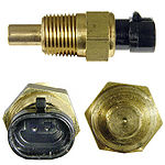
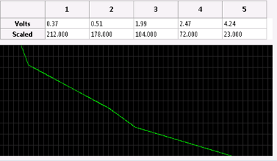
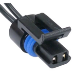
3/8" NPT threaded brass body and a 2 pin terminal. | Can be used for air inlet temperature for normally aspirated engine | * Using 2.2K pullup resistor
| |||||||||||||
|
|
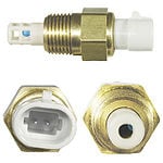
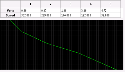
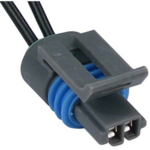
3/8" NPT threaded brass body and a 2 pin terminal. |
| ||||||||||||||
AEM | |||||||||||||||||
| AEM-30-2012 | 
|
|
|
| |||||||||||||
Infrared Sensors | |||||||||||||||||
| Mfg / Part # | Image | Notes | |||||||||||||||
| Mylexis MLX90620 | 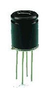
|
| |||||||||||||||
Thermocouple Sensors | |||||||||||||||||
| Analog Devices AD597 Type K Thermocouple amplifier | 
|
Low cost, easy to use thermocouple amplifier with 10mv/C temperature output directly from a K-Type thermocouple. Ideal for creating a simple thermocouple to 0-5v sensor.
| |||||||||||||||
| Maxim MAX31851 Thermocouple amplifier | 
|
Versatile thermocouple amplifier with 1-wire (I2C) digital interface. Ideal for monitoring multiple sensors
| |||||||||||||||
Pressure Sensors | |||||||||||||||||
Fluid Pressure | |||||||||||||||||
| These sensors are appropriate for measuring fluid pressures in an engine. Not appropriate for measuring manifold boost or vacuum as these are relative pressure sensors. Use an absolute pressure sensor instead. | |||||||||||||||||
| Mfg / Part # | Image | Pigtail | Mechanical | Notes | Analog Channel Configuration | ||||||||||||
| AEM 30-2131-150 | 
|
3 pin GM connector | 1/8" NPT |
|
| ||||||||||||
| Various | 
|
3 pin GM connector | 1/8" NPT port |
| |||||||||||||
Manifold Pressure (MAP) Sensors | |||||||||||||||||
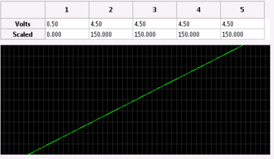
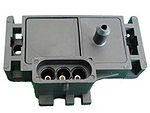
|

|
|
3 bar MAP sensor |
| |||||||||||||
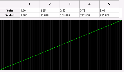
| Freescale MXP4250AP | 2.5 bar MAP sensor
|
||||||||||||||||
Tire Pressure | |||||||||||||||||
| Mfg / Part # | Image | Notes | |||||||||||||||
| Schrader |
| ||||||||||||||||
Pulse/Speed/RPM Sensors | |||||||||||||||||
RPM | |||||||||||||||||
| Mfg / Part # | Image | Notes | |||||||||||||||
| Autosport Labs CoilX | <image> | The CoilX sensor module is designed to safely interface the noisy, high voltage RPM signal at the ignition coil pack primary into a clean signal that RaceCapture/Pro can process. | |||||||||||||||
Wheel Speed / Gear speed | |||||||||||||||||
| Hall effect speed sensors will require an external 1K pull-up resistor, connected to 5v. This can be wired up near the sensor connection for convenience. | |||||||||||||||||
| Mfg / Part # | Image | Pigtail | Mechanical | Notes | Pulse Channel Configuration | ||||||||||||
| Cherry GS102301 |
|
| |||||||||||||||
| Cherry GS100701 |
| ||||||||||||||||
Distance Sensors | |||||||||||||||||
Ride Height | |||||||||||||||||
| Mfg / Part # | Image | Pigtail | Notes | Analog Channel Configuration | |||||||||||||
| Sharp GP2D12 | 
|
|
Steps to calibrate:
| ||||||||||||||
|

|

|
| ||||||||||||||
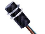
| Texense RHS | 
|
| |||||||||||||||
| KA Sensors RHL3 | 
|
| |||||||||||||||
| Various Mfg / String Potentiometer | 
|
String Potentiometers can be used for a variety of purposes: Linear, distance, and rotation (if cable is wrapped around a shaft) | |||||||||||||||
Angle / Rotation Sensors | |||||||||||||||||
Throttle Position (TPS) | |||||||||||||||||
| Mfg / Part # | Image | Pigtail | Mechanical | Notes | Analog Channel Configuration | ||||||||||||
| Ford / SMP TH45 | Screw mounted, keyed input for throttle shaft |
Common Ford style Throttle Position sensor |
To calibrate, note the voltage at 0% throttle and then at 100% throttle. Use these two numbers to create a 2 point analog scaling map. | ||||||||||||||
Wiring
Temperature Sensor
Temperature sensors are passive devices that measure temperature through the use of a thermistor, a resistor that varies resistance with temperature.
We recommend using dedicated, two wire ECU-style sensor similar to the types specified in our recommended sensor list for best results.

Pullup resistor
A pullup resistor is needed to create the necessary voltage divider circuit so RaceCapture/Pro's analog input can measure temperature as a varying voltage. This pullup resistor is connected to the 5v reference on the RaceCapture/Pro terminal block.
High Resistance ECU style sensors
Use a 2.2K ohm pull-up resistor for high resistance ECU style sensors, such as the temperature sensors in the supported list
Low Resistance Gauge type sensors
Low resistance gauge type sensors are not recommended. If you must use one of these types of sensors, a 1/4 watt 220 ohm pull-up resistor can be used for sensors such as VDO 323-095, 325-002 and similar.
Sensor Ground
Two wire ECU style temperature sensors have one sense lead and one ground lead. For best accuracy, connect the ground lead to the same ground point as RaceCapture/Pro.
One wire gauge type sensors have the ground as the body of the sensor. Ensure the engine is properly grounded to the chassis via multiple ground straps.
Active Sensors
Active sensors are powered devices that provide a variable voltage output related to the environment being measured- such as pressure, distance, temperature, speed, force, etc.

Active sensors are particularly easy to wire. Nearly all active sensors for automotive applications specify 5v power and produce an output within 0 to 5v, making them directly compatible with RaceCapture/Pro. Most active sensors have a linear output and therefore are very easy to calibrate.
Steps for connecting an active sensor
- Identify the power, ground and output signal wires. The sensor technical documentation will provide this information.
- Connect the sensor ground to the same location as the ground point for RaceCapture/Pro
- If the sensor is 5v powered, connect it to the 5v voltage reference on RaceCapture/Pro
- Connect the sensor output signal to the desired analog input port of RaceCapture/Pro
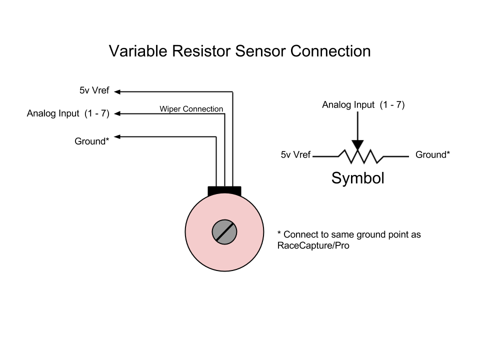
Throttle Position / Variable Resistors (Potentiometers) / Linear sensors
These type of sensors are passive devices comprising some form of a variable resistor. Examples include:
- Throttle Position Sensors
- Linear sensors
- String Potentiometers
- Single and multi-turn Potentiometers
Steps for connecting an variable resistance type sensor
- Consult the sensor's technical documentation for sensor connections.
- Connect one of the outside legs of the variable resistor to the ground point for RaceCapture/Pro
- Connect the opposite leg of the variable resistor to the 5v Vref of RaceCapture/Pro
- Connect the variable resistor wiper (typically the center lead) to the the desired analog input port of RaceCapture/Pro
During calibration, if the sensor reads backwards, flip the 5v and ground connections.
Sensor Breakout Board
We've created an optional sensor breakout / distribution board that will make it easier to use sensors that require pullup resistors as well as making available multiple ground and 5V Vref connections. The built-in pullup resistors are easily disabled by breaking a designated trace on the board. This board is compact; enough to be bundled inline with your wiring harness.

Hardware Expansion board <coming soon> look for it to fit into the RJ-45 jack in the back of the RaceCapture Pro. It can be used to develop your own sensors, or hook in some of the cleverer concepts we've come up with!
Adapter Board <coming soon> look for it to fit into the GPIO pins on the green removable bus in the back of the RaceCapture Pro.

