AIM CAN: Difference between revisions
| (3 intermediate revisions by one other user not shown) | |||
| Line 1: | Line 1: | ||
=AIM Solo DL= | |||
AIM Solo DL research is underway. | |||
=MyChron 4= | =MyChron 4= | ||
MyChron 4 | MyChron 4 research is underway. | ||
=MyChron 3= | =MyChron 3= | ||
| Line 7: | Line 10: | ||
[[File:AIM_Mychron3.jpg|500px]] | [[File:AIM_Mychron3.jpg|500px]] | ||
== Wiring / Connection== | |||
TODO: show wiring and connection information between RaceCapture/Pro and Mychron3 | |||
== CAN Bus Initialization == | == CAN Bus Initialization == | ||
The AIM Mychron3 requires a CAN bus rate of 1Mb/s, in standard form (11 bit identifiers). The following code example initializes the CAN bus channel at 1Mb/s. | The AIM Mychron3 requires a CAN bus rate of 1Mb/s, in standard form (11 bit identifiers). The following code example initializes the CAN bus channel #2 at 1Mb/s. | ||
initCAN(2, 1000000) | initCAN(2, 1000000) | ||
== Packet 401h: RPM, Speed, Gear blink control, Gear == | == Packet 401h: RPM, Speed, Gear blink control, Gear == | ||
Latest revision as of 21:33, 10 January 2015
AIM Solo DL
AIM Solo DL research is underway.
MyChron 4
MyChron 4 research is underway.
MyChron 3
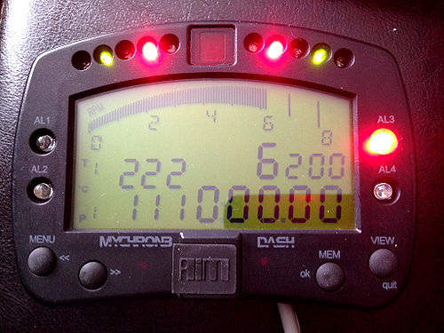
This section documents how to control an AIM Mychron3 Dash display, using a RaceCapture/Pro telemetry system unit via LUA scripting. The following information is a sum up of reverse engineering findings by Jean-Sebastien Stoezel documented here. Examples of LUA implementation of the the different packets documented on the Mychron 3 Hack page are provided below.
Wiring / Connection
TODO: show wiring and connection information between RaceCapture/Pro and Mychron3
CAN Bus Initialization
The AIM Mychron3 requires a CAN bus rate of 1Mb/s, in standard form (11 bit identifiers). The following code example initializes the CAN bus channel #2 at 1Mb/s.
initCAN(2, 1000000)
Packet 401h: RPM, Speed, Gear blink control, Gear
 function onTick()
   local rpm = getTimerRpm(0)
   local speedmph = getGpsSpeed()
   -- Assume the gear is calculated and stored in a virtual channel.
   -- Refer to LUA scripting example to calculate the gear based on speed and RPM
   local gear = getChannel(gearId)
   local msg = {rpm % 256, rpm / 256, (speedmph % 16) % 256, (speedmph / 16) / 256, 0, 0, gear, 0}
   txCAN(0, 1025, 0, msg)
 end
Packet 402h: Temperature/Pressure fields (bottom left of display)
 function onTick()
   -- Assume different temperature values are connected to different sensors
   local temp1 = getAnalog(0)
   local temp2 = getAnalog(1)
   local temp3 = getAnalog(2)
   local temp4 = getAnalog(3)
   local msg = {temp1 % 256, temp1 / 256, temp2 % 256, temp2 / 256, temp3 % 256, temp3 / 256, temp4 % 4, temp4 / 256}
   txCAN(0, 1026, 0, msg)
end
Packet 405h: Shift LEDs, Alarm LEDs
 function onTick()
   local shiftLeds = 0
   local rpm = getTimerRpm(0)
   if rpm > 5000 then shiftLeds = shiftLeds + 1 end
   if rpm > 6000 then shiftLeds = shiftLeds + 2 end
   if rpm > 7000 then shiftLeds = shiftLeds + 4 end
   if rpm > 7500 then shiftLeds = shiftLeds + 8 end
   if rpm > 7700 then shiftLeds = shiftLeds + 16 end
   local msg = {0, 0, 0, 0, 0, 0, shiftLeds, 0}
   txCAN(0, 1029, 0, msg)
 end
Packet 406h: RPM range for the digital RPM readout
 function onTick()
   -- Set the RPM range
   -- Value  	 RPM Range
   -- 0	 25,000 - 0
   -- 1	 22,000 - 0
   -- 2	 20,000 - 0
   -- 3	 16,000 - 0
   -- 4	 12,000 - 0
   -- 5	 10,000 - 0
   -- 6	 8,000 - 0
   -- 7	 6,000 - 0
   -- 8	 4,000 - 0
   local rpmRange = 6 -- Up to 8000 RPM
   local msg = {0, rpmRange * 16, 0, 0, 0, 0, 0, 0}
   txCAN(0, 1030, 0, msg)
 end

