RaceCapture-Pro MK4S Sensors: Difference between revisions
| Line 170: | Line 170: | ||
* '''Pinout :''' Pin A : Ground || Pin B : Signal || Pin C : Power | * '''Pinout :''' Pin A : Ground || Pin B : Signal || Pin C : Power | ||
* '''Output :''' 0.619V to 4.818 VDC<br> | * '''Output :''' 0.619V to 4.818 VDC<br> | ||
<br> | |||
<br> | <br> | ||
'''[Freescale MXP4250AP : 2.5 bar Manifold Absolute Pressure Sensor ]'''<br> | |||
'''[Freescale MXP4250AP : 2.5 bar Manifold Absolute Pressure Sensor ]''' | |||
[[Image:Freescale-Semiconductor-MPX4250AP.jpg|200px|thumb|right]] | [[Image:Freescale-Semiconductor-MPX4250AP.jpg|200px|thumb|right]] | ||
The specification of the sensor are as follows. | |||
* '''Mfg / Prt :''' Freescale MXP4250AP | * '''Mfg / Prt :''' Freescale MXP4250AP | ||
* '''Operating Pressure :''' 20 to 250 kPa | * '''Operating Pressure :''' 20 to 250 kPa | ||
Revision as of 21:30, 6 December 2023
Temperature Sensors
Temperature sensors are passive devices that measure temperature through the use of a thermistor, a resistor that varies resistance with temperature. We recommend using dedicated, two wire ECU-style sensor similar to the types specified in our recommended sensor list for best results.

Pullup Resistor
A pullup resistor is needed to create the necessary voltage divider circuit so RaceCapture/Pro's analog input can measure temperature as a varying voltage. This pullup resistor is connected to the 5v reference on the RaceCapture/Pro terminal block.
High Resistance ECU style sensors Use a 2.2K ohm pull-up resistor for high resistance ECU style sensors, such as the temperature sensors in supported list
Low Resistance Gauge type sensors Low resistance gauge type sensors are not recommended. If you must use one of these types of sensors, a 1/4 watt 220 ohm pull-up resistor can be used for sensors such as VDO 323-095, 325-002 and similar.
Sensor Ground
Two wire ECU style temperature sensors have one sense lead and one ground lead. For best accuracy, connect the ground lead to the same ground point as RaceCapture/Pro. One wire gauge type sensors have the ground as the body of the sensor. Ensure the engine is properly grounded to the chassis via multiple ground straps.
Recommended GM-Style Temperature Sensor
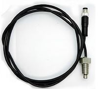
[ASL_LINEAR_TEMP_M8 : -40 to 150C Linear temperature sensor ]
The specification of the sensor are as follows.
- Mfg / Prt : ASL_LINEAR_TEMP_M8
- Thread Size : 1/8″ NPT
- Cable length : 1 Meter
- Pigtail / Harness connector : M8
- Analog Channel Configuration : Preset available in the RaceCapture app
- Pull up resistor : Not required
- Voltage supply : 3-5V
- Pinout : Pin 1 : Ground || Pin 2 : 5V || Pin 3 : Signal Output
- Body Material : Stainless Steel
- Uses : The sensor is suitable for fluids such as oil, coolant and water
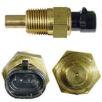
[ Wells SU109 || SMP TX3 : Engine Coolant Temperature Sensor ]
The specification of the sensor are as follows.
- Mfg / Prt : Wells SU109 || SMP TX3
- Thread Size : 3/8" NPT
- Cable length : N/A
- Pigtail : Pico 5615pt ( 2 pin terminal )
- Analog Channel Configuration : Preset available in the RaceCapture app
- Pull up resistor : 2.2K pullup resistor
- Body Material : Copper
- Uses : Used for air inlet temperature for normally aspirated engine
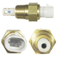
[ Wells SU107 || SMP TX3 : Air Intake / Charge Temperature Sensor]
The specification of the sensor are as follows
- Mfg / Prt : Wells SU107 || SMP AX1
- Thread Size : 3/8" NPT
- Pigtail :Pico 5616pt
- Analog Channel Configuration : Preset available in the RaceCapture app
- Pull up resistor : 2.2K pullup resistor
- Body Material : Brass
- Uses : Use for measuring air inlet / charge temperature measurement
- Caution : Due to the fragility of the sensing bulb, it is necessary to pot the base of the sensor leads with sensor-safe silicone when used in high vibration environments.
Recommended Delphi-Style Temperature Sensor
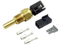
[ Delphi 12160855 || AEM-30-2012 : Extended temperature range sensor ]
The specifications are as follows.
- Mfg / Prt : Delphi 12160855 equivalent || AEM-30-2012 Equivalent
- Thread Size : 1/8" - 27 NPTF
- Matting Connector : 12047662 connector
- Analog Channel Configuration : Preset available in the RaceCapture app
- Pull up resistor : 2.2K pullup resisto
- Voltage supply : 5V
- Body Material : Brass (PA66)
- Uses : Extended temperature range suitable for coolant and oil
Pressure Sensors
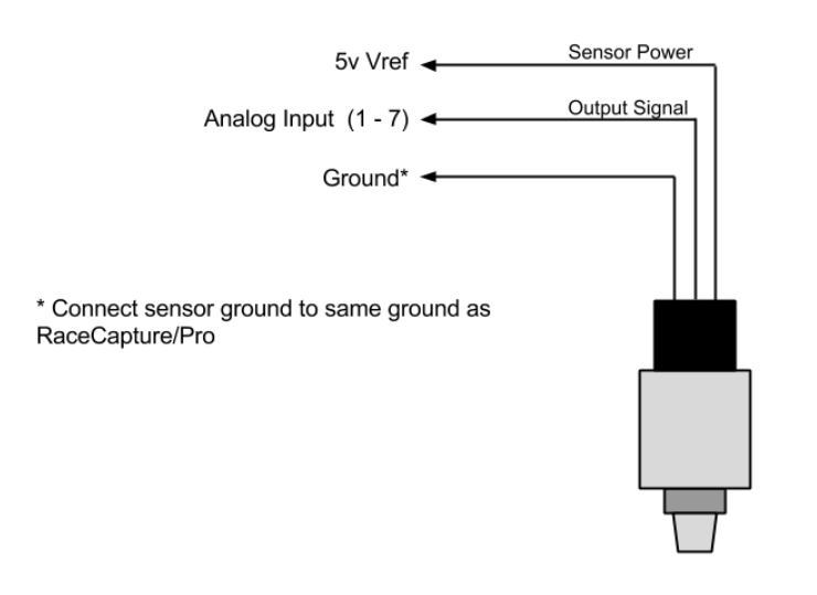
Pressure sensors are powered devices and are a type of active sensors. They provide a variable voltage output. Pressure sensors are particularly easy to wire. Nearly all Pressure Sensors, active sensors, for automotive applications specify 5v power and produce an output within 0 to 5v, making them directly compatible with RaceCapture/Pro. Most pressure sensors have a linear output and therefore are very easy to calibrate.
Steps for connecting pressure sensors
- Identify the power, ground and output signal wires. The sensor technical documentation will provide this information
- Connect the sensor ground to the same location as the ground point for RaceCapture/Pro
- If the sensor is 5v powered, connect it to the 5v voltage reference on RaceCapture/Pro
- Connect the sensor output signal to the desired analog input port of RaceCapture/Pro
Recommended Fluid Pressure Sensors
Note : These sensors are appropriate for measuring fluid pressures in an engine. Not appropriate for measuring manifold boost or vacuum as these are relative pressure sensors. Use an absolute pressure sensor instead.
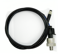
[ASL_10_BAR_DELPHI3_M8 : 10 bar / 150 PSI pressure sensor ]
The specification of the sensor are as follows.
- Mfg / Prt : ASL_10_BAR_DELPHI3_M8
- Thread Size : 1/8″ NPT
- Cable length : 2 Meter
- Harness connector : M8 plug and play harness connector
- Analog Channel Configuration : Preset available in the RaceCapture app
- Pull up resistor : Not required
- Voltage supply : 5V
- Pinout : Pin 1 : Ground || Pin 2 : 5V || Pin 3 : Signal Output
- Body Material : Stainless Steel
- Output : Linear response output between 0.5v and 4.5v
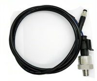
[ASL_150_BAR_DELPHI3_M8 : 150 bar / 2175 PSI pressure sensor ]
The specification of the sensor are as follows.
- Mfg / Prt : ASL_150_BAR_DELPHI3_M8
- Thread Size : 1/8″ NPT
- Cable length : 2 Meter
- Harness connector : M8 plug and play harness connector
- Analog Channel Configuration : Preset available in the RaceCapture app
- Pull up resistor : Not required
- Voltage supply : 5V
- Pinout : Pin 1 : Ground || Pin 2 : 5V || Pin 3 : Signal Output
- Body Material : Stainless Steel
- Output : Linear response output between 0.5v and 4.5v
- Use :Typically used for high pressure sensing, such as brake or clutch pressure
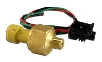
[AEM 30-2131-150 : 150 PSI pressure sensor ]
The specification of the sensor are as follows.
- Mfg / Prt : AEM 30-2131-150
- Thread Size : 1/8″ NPT
- Pigtail : 3 pin GM connector
- Analog Channel Configuration : Preset available in the RaceCapture app
- Body Material : Brass
- Output : Linear response with an output between 0.5v and 4.5v
- Use :Appropriate for oil and fuel pressure measurement
Recommended Manifold Pressure (MAP) Sensors
[12223861 (GM) : Manifold Absolute Pressure MAP Sensor ]
The specification of the sensor are as follows.
- Mfg / Prt : 12223861 (GM)
- Pigtail : 15305891 (GM) or PT1035 (AC Delco)
- Operating Pressure : 40 TO 304 kPa
- Voltage supply : 5.1 +/- 0.36 V
- Analog Channel Configuration : Preset available in the RaceCapture app
- Pinout : Pin A : Ground || Pin B : Signal || Pin C : Power
- Output : 0.619V to 4.818 VDC
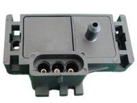
[Freescale MXP4250AP : 2.5 bar Manifold Absolute Pressure Sensor ]
The specification of the sensor are as follows.
- Mfg / Prt : Freescale MXP4250AP
- Operating Pressure : 20 to 250 kPa
- Voltage supply : 4.85 to 5.35 VDC
- Analog Channel Configuration : Preset available in the RaceCapture app
- Pinout : Pin A : Ground || Pin B : Signal || Pin C : Power
- Output : 0.2 to 4.9 V
- Use : An extremely popular MAP sensor used in the Megajolt ignition and Megasquirt fuel injection systems.
Pulse/Speed/RPM Sensors
Wheel speed sensors generate a series of pulses as a toothed wheel passes by the face of the sensor. We recommend hall-effect style sensors, and these are provided with 3 connections:
- Power
- Ground
- Signal Output
Note: - We do not recommend using 2 wire Variable Reluctance (VR) type sensors. VR Sensors will require a conditioning circuit before being provided to the inputs of RaceCapture/Pro.
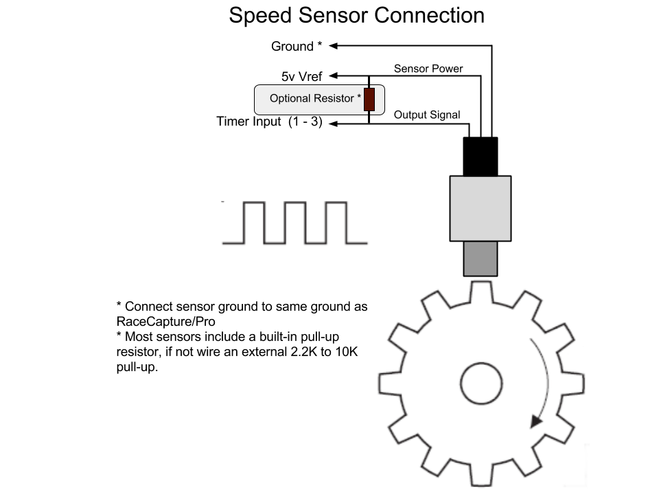
Wiring the Speed Sensor
- Power : Connect the sensor's power to the 5v Vref on RaceCapture/Pro
- Ground : Connect the sensor's ground connection to the ground shared by RaceCapture/Pro
- Sensor Output : Connect the Sensor Output to one of RaceCapture/Pro's timer input channels
Optional pull up resistor RaceCapture/Pro requires both a voltage and ground pulse provided in the waveform provided by the sensor. Most sensors provide an internal pull-up resistor so an active square wave can be observed on the output. However, some sensors only switch ground and leave the output line in a high impedance state when not active, like opening and closing a mechanical switch. If the sensor does not provide a pull-up resistor the wheel speed signal may have noise and glitches which may be observed as high value glitches in the dashboard and log file data.
If it's determined a pull-up resistor is needed:
- Use 2.2 to 10K pull-up resistor can be added close to RaceCapture/Pro to ensure a clear signal
- You can use the SensorX breakout board to conveniently wire this pull-up resistor
Recommended RPM Sensor
[Autosport Labs CoilX RPM Input adapter ]
The specification of the sensor are as follows.
- Mfg / Prt : ASL_COILX
- Input Connection : Red: Coil Signal || Black: Ground (External)
- Output/ To Realitycapture : Yellow: 5v power || Black: Output || Red: Ground (data system)
- Analog Channel Configuration : Preset available in the RaceCapture app
- Caution : Do not exceed 5 volts or damage to module will occur
- Use : The CoilX sensor module is designed to safely interface the noisy, high voltage RPM signal at the ignition coil pack primary into a clean signal that RaceCapture/Pro can process.
Recommended Wheel Speed / Gear speed Sensors
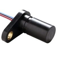
[Hamlin 55505 : Hall Effect Flange Mount Geartooth Sensor ]
The specification of the sensor are as follows.
- Mfg / Prt : Hamlin 55505
- Pullup resistor : Simple 3 wire hookup - No external pullup resistor required
- Pulse Channel Configuration : Configure the pulse channel with the number of pulses per revolution, which maps to the number of teeth on the gear / wheel.
- Supply Voltage : 4.75 to 24 V
- Supply Current : 1 to 10.5 mA
- Operating Temperature : -40 to 125c
- Use : Rugged Hall effect sensor suitable for harsh automotive environments (fuels, solvents, lubricants)
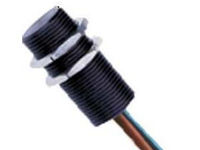
[Cherry GS100701 : GS100701 Gear Speed Sensor ]
- Mfg / Prt : Cherry GS100701
- Thread Size : 15/32-32
- Pulse Channel Configuration : Configure the pulse channel with the number of pulses per revolution, which maps to the number of teeth on the gear / wheel.
- Supply Voltage : 5 to 24 V
- Supply Current : 3 to 6 mA
- Operating Temperature : -40 to 125c
- Body Material : Aluminum
- Output current : 25mA max
Distance Sensors
Distance sensors are also a type of active sensors, except string potentiometer sensor, which is a passive device. Distance sensors also provide variable voltage output. These sensors are particularly easy to wire. Nearly all distance Sensors, active sensors, for automotive applications specify 5v power and produce an output within 0 to 5v, making them directly compatible with RaceCapture/Pro. Most pressure sensors have a linear output and therefore are very easy to calibrate.
Steps for connecting distance sensors
- Identify the power, ground and output signal wires. The sensor technical documentation will provide this information
- Connect the sensor ground to the same location as the ground point for RaceCapture/Pro
- If the sensor is 5v powered, connect it to the 5v voltage reference on RaceCapture/Pro
- Connect the sensor output signal to the desired analog input port of RaceCapture/Pro
Recommended Ride Height Sensors
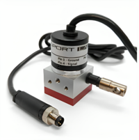
[ASL_STRING_POT_M8 : 500mm string potentiometer sensor]
The specification are as follows.
- Mfg / Prt : ASL_STRING_POT_M8
- Measurement Range : Up to 2 meters,
- Draw Cable : 500mm stainless steel draw cable
- Connector : M8 3P connector, works with our plug and play harness system
- Cable : 2 meter cable
- Range : 10K ohm range
- Pinout : Pin 1 : Ground || Pin 2 : Ground || Pin 3 : Signal
- Mount Type : Three mounting holes available for mounting
- Uses : Used to measure steering angle or linear travel
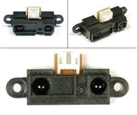
[ Sharp GP2D12 : IR Range Sensor]
The specification are as follows.
- Mfg / Prt : Sharp GP2D12
- Detecting Range : 10-80cm
- Connection : 3 Pin JST cable
- Pinout : Pin 1 : Signal || Pin 2 : Ground || Pin3 : Power
- Voltage supply : -0.3 to 7.0 V
- Average current consumption: 33 mA
- Output Terminal Voltage : -0.3 to (VCC + 0.3)
- Uses : Used for ride height position (pointed at ground) and pedal position measurement
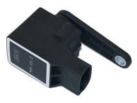
[ BMW 37140141444 : Height Level Sensor]
The specification are as follows.
- Mfg / Prt : BMW 37140141444
- Pigtail : 61138383300
- Measurement Range : Measures distance over 90 degrees of the arm travel.
- Pinout : Pin 1 : Signal || Pin 2 : Ground || Pin3 : Power
- Voltage Supply : 5V
- Output Terminal Voltage : 0-5v
- Uses : Used as a ride-height sensor for BMW and Mini applications for auto-leveling headlights
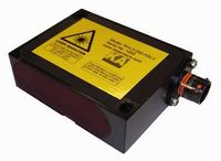
[ KA Sensors RHL3 : Laser Ride Height Sensor] The specification are as follows.
- Mfg / Prt : BMW 37140141444
- Electrical Connection : Cable: 26AWG, 55spec wire+DR25 sleeve or ASL Conn.
- Measurement Range : 200mm (60-260) or 500mm (200-700)
- Pinout : Red (Pin1) : +Ve Supply || Black (Pin 2) : Ground || White (Pin 3) : Signal || Pin 4 & 5 : Not Connected
- Voltage Supply : 11-30v (50mA) ( Separate power supply required )
- Output Terminal Voltage : 1-5v
- Body Material : Aluminum
Analog Channel Configuration of Ride Height Sensors
Note : Please follow the below instruction for all the ride height sensors analog channel configuration.
Step To Calibrate :
- After installation place the vehicle on a level surface
- Set the Analog calibration to 0-5v simple linear scaling
- At rest, note the voltage of the sensor. This is the zero level.
- Raise and safely support the corner of the vehicle and remove the spring.
- Move the suspension arm to full droop. Note actual inches / mm traveled and also note the voltage logged by RaceCapture/Pro
- Move the suspension arm to full compression. Note actual inches / mm and also note the voltage logged by RaceCapture/Pro
Create Calibration Table:
- Place the droop voltage / distance combination into the 1st column of the calibration table. Make the distance negative
- Place the 'at rest' voltage into the 2nd column of the calibration table. Make the distance zero
- Place the compression voltage / distance into the 3rd column of the calibration table. Make the distance positive
- Repeat the compression voltage / distance values for the 4th and 5th columns
Angle/Rotation Sensors
These type of sensors are passive devices comprising some form of a variable resistor.
Steps for connecting Angle/Rotation Sensors
- Consult the sensor's technical documentation for sensor connections.
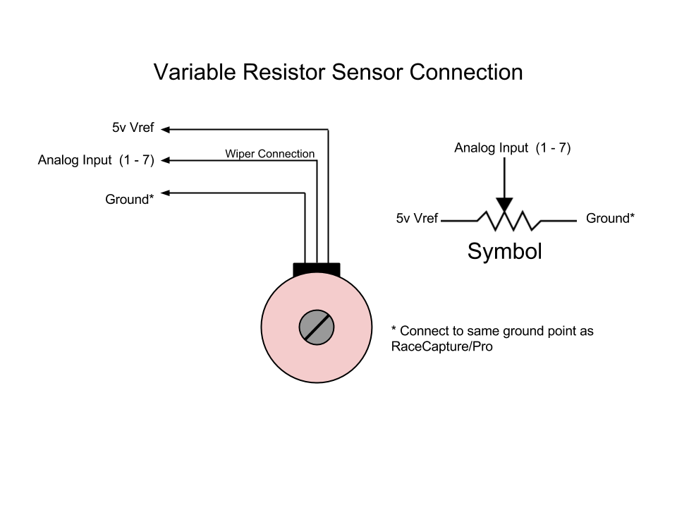
- Connect one of the outside legs of the variable resistor to the ground point for RaceCapture/Pro
- Connect the opposite leg of the variable resistor to the 5v Vref of RaceCapture/Pro
- Connect the variable resistor wiper (typically the center lead) to the the desired analog input port of RaceCapture/Pro
- During calibration, if the sensor reads backwards, flip the 5v and ground connections.
Note : Users can follow the same instruction for connecting string Potentiometer
Recommended Throttle Position (TPS) Sensor
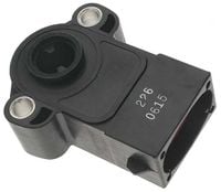
[Ford / SMP TH45 : Throttle Position Sensor]
The specifications are as follows.
- Mfg/Prt : Ford / SMP TH45
- Pigtail : Pico 5752PT
- Supply Voltage : 5V
- Analog Channel Configuration :To calibrate, note the voltage at 0% throttle and then at 100% throttle. Use these two numbers to create a 2 point analog scaling map
- Use : Common Ford style Throttle Position sensor
Air & Fuel Ratio/ Level Sensor
Fuel Level Sensors are also variable resistor, these provide variable resistance based on the level of the float.
Wiring
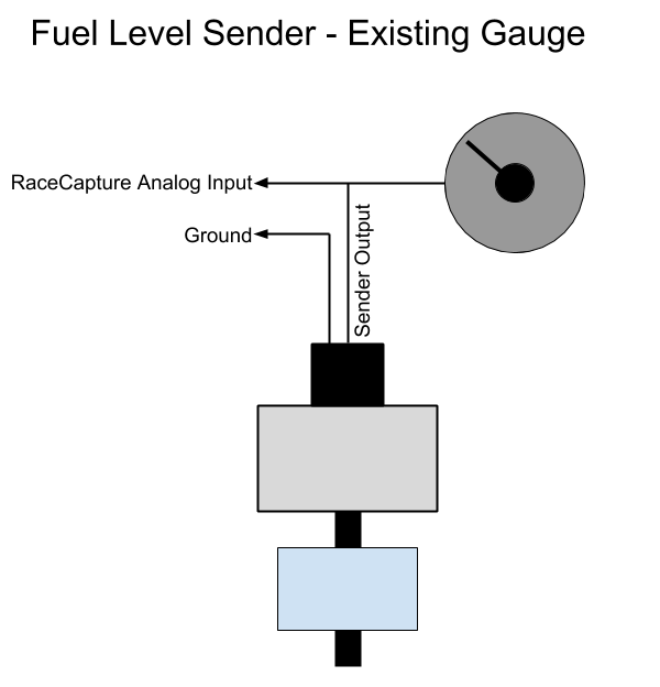
Determine if you need a pullup resistor, or if you are tapping into an existing circuit with a gauge.
If you already have a gauge connected, you will not need a pullup resistor - the gauge's internal circuitry already provides one. You will only need to tap into the existing signal feeding the fuel gauge sender. Jump to the calibration process below.
Note : You will need to ensure the sender does not exceed 5v during calibration. if it does, you will need an additional voltage divider to scale the voltage down to 0-5v required by the RaceCapture input.
If you have no gauge / you want to only use RaceCapture for your dashboard gauge, want to directly integrate with RaceCapture's analog input, follow this procedure.
- Choose a pull-up resistor value based on the the sender's ohm range. If it is less than 1000 ohms, then choose a 1000 (1K) ohm resistor as your pull-up. If the sender range is higher than 1000 ohms, choose a 2.2K resistor
- Rule of thumb - choose a resistor that is about 2X to 4X the maximum resistance of the sender
- A 1/2 watt, 1% accuracy resistor is recommended
- Wire up the sender per the diagram:
- Connect the ground of the fuel level sender to ground (ideally the same ground point used by RaceCapture)
- Connect the output of the sender to one of RaceCapture's analog inputs
- Connect the pullup resistor between +5v reference and the sender's output. This creates the voltage divider circuit which will present RaceCapture with a variable voltage depending on fuel level.
Recommended Air / Fuel Ratio Sensor
[Texense LSU 4.9 : Air / Fuel Ratio Sensors]
The specifications are as follows.
- Mfg/Prt : Texense LSU 4.9
- Pigtail : Built-in wiring
- Fitting : Screws into O2 sensor port
- Analog Channel Configuration : Preset available in the RaceCapture app
- Use : Use to measure the oxygen ratio in the exhaust gas of automobile engines (petrol or diesel)
Wiring Analog Sensors
RaceCapture/Pro Analog Input Specifications
- Total Analog Inputs : 8 ( the 8th input is wired internally to measuring battery voltage.)
- Analog Input Voltage Range : 0 to 5V
- Input Impedance : Over 1 mega ohm
Calibrating Analog Sensors
Linear Sensors
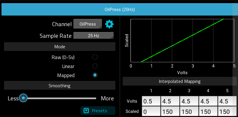
A linear sensor specify two voltages/value pairs representing a low and high range for the sensor. A straight line is drawn between the points on the sensor.
Example : 150 PSI pressure sensor
- 0.5 v = 0 PSI
- 4.5 v = 150 PSI
In the Analog Channel configuration, select the "'Mapped"' sensor mode, and then enter the values into the interpolated mapping grid.
- For column 1, enter the low voltage range in the Volts cell, and the low scaled value in the Scaled cell.
- For columns 2-5 enter the high voltage range in the Volts cell, and the high scaled value in the Scaled cell
Curved Sensors
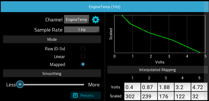
Curved sensors are usually thermistor based sensors, where the response is not a straight line, but a curve. Multiple points can be used to sufficiently approximate the curve.
Note : RaceCapture linearly interpolates the scaled values between the sensor points, so value transitions will be smooth.
Example : Extended range temperature sensor with 5v reference and 2.2K pullup resistor
- 0.4 v = 302 F
- 0.87 v = 239 F
- 1.88 v = 176 F
- 3.2 v = 122 F
- 4.72 v = 32 F
In the Analog Channel configuration, select the Mapped sensor mode, and then enter the values into the interpolated mapping grid.
Note : If you have more than 5 points for the curve, spread the selection of points evenly between your low and high range.
Fuel Level Sensors
Fuel Level Sensors are usually variable resistance based sensors, and provide a variable resistance based on the level of the float.
Calibration With the fuel at different levels, measure and note the voltage present at the RaceCapture analog input for different fuel levels:
- Empty (0%)
- 1/4 (25%)
- 1/2 (50%)
- 3/4 (75%)
- Full (100%)
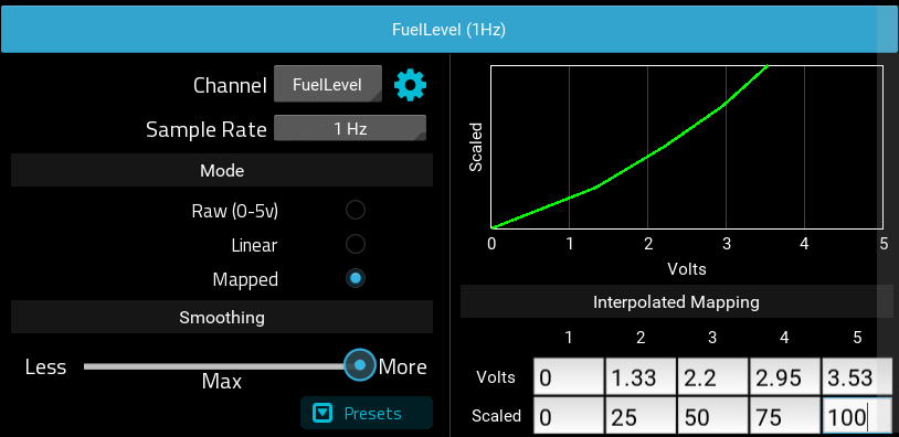
Set up the Analog Channel
- Choose an available analog input for your Fuel Level channel, then select the basic fuel level preset by selecting FuelLevel in the dropdown list. (This pre-sets the units (%), logging precision and min / max values. You can edit this by pressing the gear button next to the channel name
- Set the sample rate to 1Hz.
- Set the mode to Mapped. This will let you create a curved mapping for the sensor voltage.
- Set the smoothing to Maximum - this will help account for variances due to fuel slosh.
- Enter the mapped values noted in the calibration process into the Analog Channel mapping editor under RaceCapture setup. This will provide the calibration curve for your fuel tank.
- Write these settings back to RaceCapture and observe your fuel level readings in units of percentage.
Example BMW E36 fuel level mapping
Example BMW E36 Fuel curve mapping (your sender's calibration will be different)

