TachAdapter: Difference between revisions
No edit summary |
|||
| (2 intermediate revisions by the same user not shown) | |||
| Line 9: | Line 9: | ||
===Installation=== | ===Installation=== | ||
Installation | Installation: | ||
* Connect Coil 1,2,3 and 4 to the drive signals to each coil packs as necessary. | * Connect Coil 1,2,3 and 4 to the drive signals to each coil packs as necessary. | ||
** We recommend 24 gauge wire, but wire gauge is not critical- so long as it fits the module. | |||
* Connect the tach output to the input of your tachometer. | * Connect the tach output to the input of your tachometer. | ||
* | * Seal the module with shrink tubing or electrical tape- the board is small enough to integrate into your wire harness / bundle. | ||
===Example Wiring=== | ===Example Wiring=== | ||
| Line 20: | Line 21: | ||
===Schematics=== | ===Schematics=== | ||
[[Image:tach_adapter_sch.png]] | [[Image:tach_adapter_sch.png|left|thumb|500px]] | ||
Latest revision as of 17:38, 13 March 2015
Tachometer Adapter
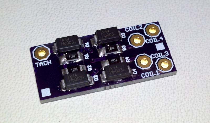
This small board adapts a Tachometer to up to 4 individual coil packs, capable of handling 4, 6 or 8 cylinder wasted spark applications.
Available for purchase in our Online Store
Installation
Installation:
- Connect Coil 1,2,3 and 4 to the drive signals to each coil packs as necessary.
- We recommend 24 gauge wire, but wire gauge is not critical- so long as it fits the module.
- Connect the tach output to the input of your tachometer.
- Seal the module with shrink tubing or electrical tape- the board is small enough to integrate into your wire harness / bundle.
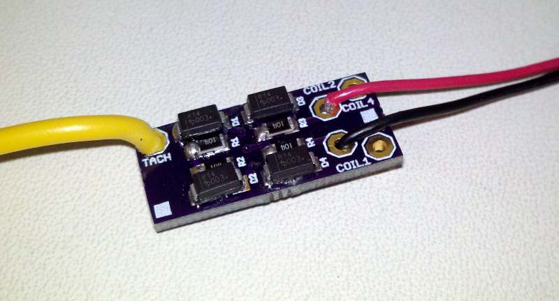
Example Wiring
Example wiring for a 4 cylinder wasted spark application: yellow wire connects to Tachometer input; red and black wire connect to the drive signals for the coil packs.


