Hard rev limiter 1.2.0: Difference between revisions
(removed extraneous V3 Controller heading) |
|||
| (10 intermediate revisions by the same user not shown) | |||
| Line 23: | Line 23: | ||
===Board=== | ===Board=== | ||
The module is housed on a small, low profile board with the exclusive use of rugged surface mount components. The board is sized to slide into one of the available slots of the MJLJ enclosure; or you can mount it to suit your application. | The module is housed on a small, low profile board with the exclusive use of rugged surface mount components. The board is sized to slide into one of the available slots of the MJLJ enclosure; or you can mount it to suit your application. | ||
[[Image: | [[Image:hard_rev_lim_assembled_1.2.0.jpg|center]] | ||
==Assembling the kit== | ==Assembling the kit== | ||
| Line 31: | Line 31: | ||
<center> | <center> | ||
[[Image:essential_smt_solder_tools.jpg]] | [[Image:essential_smt_solder_tools.jpg]] | ||
<br> | |||
[[Image:illuminated_magnifying_glass.jpg]] | |||
<br>''The essential tools for SMT work'' | <br>''The essential tools for SMT work'' | ||
</center> | </center> | ||
| Line 37: | Line 39: | ||
*Probably the best tool - a cross-action set of tweezers. This tool is normally closed, allowing you to hold parts with a relaxed grip and reduced tremors. | *Probably the best tool - a cross-action set of tweezers. This tool is normally closed, allowing you to hold parts with a relaxed grip and reduced tremors. | ||
*Solder wick. Too much solder and you'll create ugly blobs and solder spikes. use this to clean up your joints by drawing away excess solder. | *Solder wick. Too much solder and you'll create ugly blobs and solder spikes. use this to clean up your joints by drawing away excess solder. | ||
*A magnifying glass, preferably illuminated, is useful for identifying package markings and inspecting solder joints. | |||
<center> | <center> | ||
| Line 64: | Line 67: | ||
===Surface mount soldering=== | ===Surface mount soldering=== | ||
Soldering lead-less surface mount components | Soldering lead-less surface mount components usually involves tacking one lead down to the board to fix it in place and then working on the remaining leads. With the smaller components, be careful to not apply excessive heat- just enough is needed to flow the solder into the joint. Excessive heat, at minimum, will cause small parts to slide off the pads, and at worst, can destroy them. | ||
==Installing the parts== | ==Installing the parts== | ||
| Line 101: | Line 104: | ||
===Installing supporting components=== | ===Installing supporting components=== | ||
Install Q1. | Install Q1. For kit builders, a 2N3906 PNP transistor has been supplied for ease of assembly. Insert Q1 with the orientation shown, leaving enough lead length to fold the transistor flat against the board- this will be needed to ensure low profile installations. | ||
<center> | <center> | ||
| Line 107: | Line 110: | ||
<br>''Soldering Q1'' | <br>''Soldering Q1'' | ||
</center> | </center> | ||
Using the same technique as the power resistors, install the 10K resistor for R11 and the 100K resistor for R12. Solder the other side of the resistors. | Using the same technique as the power resistors, install the 10K resistor for R11 and the 100K resistor for R12. Solder the other side of the resistors. | ||
| Line 141: | Line 142: | ||
<br>''Tacking down Q1 before soldering the remaining pins'' | <br>''Tacking down Q1 before soldering the remaining pins'' | ||
</center> | </center> | ||
===Final Inspection=== | ===Final Inspection=== | ||
| Line 156: | Line 155: | ||
==Installing the Hard Rev Limiter== | ==Installing the Hard Rev Limiter== | ||
=== | ===Physical Installation=== | ||
It's up to the user to determine how to install the rev limiter module. Following are a couple of possible installation options. | |||
Since the resistor array generates heat when rev-limiting is active, ambient temperature and air flow across the module will affect the duty-cycle of the unit- meaning how often and long you'll be able to be 'on' the rev-limiter. | |||
TODO: add duty-cycle testing results | TODO: add duty-cycle testing results | ||
| Line 174: | Line 171: | ||
====Integrating into the MJLJ enclosure==== | ====Integrating into the MJLJ enclosure==== | ||
The board | The Rev Limiter board is sized to fit both the V3 and V4 controller. Rotate the controller to fit the enclosure rails. | ||
=====V4 Controller===== | |||
Wire the Rev Limiter board to the +12V, Coil Power, Trigger and ground pads on the V4 board. Use 14 gauge wire for the +12V and Coil Power pads and 22-18 gauge wire for trigger and ground. | |||
Refer to the following for wiring and board installation: | |||
<center> | |||
[[Image:MJLJ_V4_rev_limiter_wiring.jpg]]<br> | |||
[[Image:mjlj_v4_rev_limiter_case_install_side.jpg]]<br> | |||
[[Image:mjlj_v4_rev_limiter_install_end.jpg]] | |||
</center> | |||
Slide the board into one of the slots above the main board. | |||
======External Wiring Diagram====== | |||
[[Image:hard_rev_limit_wiring_diagram.png]] | |||
With this approach, several wiring possibilities exist: | With this approach, several wiring possibilities exist: | ||
* Cut a hole in the end plate, | * Cut a hole in the end plate, and route all wires outside the case, looping back to the MJLJ wiring harness plug; | ||
* Cut a hole in the end plate, externally expose the +12v and coil pack connectors, but connect the ground and trigger with jumpers to the inside of the case. | * Cut a hole in the end plate, externally expose the +12v and coil pack connectors, but connect the ground and trigger with jumpers to the inside of the case. | ||
* Most ambitious: wire everything internally: | * Most ambitious: wire everything internally: | ||
** Jumper GND connection to MJLJ GND | ** Jumper GND connection to MJLJ GND; | ||
** Jumper +12V connection to MJLJ +12V | ** Jumper +12V connection to MJLJ +12V (14 gauge wire); | ||
** Jumper trigger input to REV_LIMIT output on MJLJ board | ** Use a thicker gauge wire (14 gauge) for MJLJ +12V power, if necessary, as the +12v supply will supply current to the coil in addition to powering the MJLJ electronics; | ||
** Cut the REV_LIMIT trace on the MJLJ board running from the ULN2003 to the REV_LIMIT connector pin. The REV_LIMIT pin will now be the new COIL power supply. | ** Jumper trigger input to REV_LIMIT output on MJLJ board; | ||
** Cut the REV_LIMIT trace on the MJLJ board running from the ULN2003 to the REV_LIMIT connector pin. The REV_LIMIT pin will now be the new COIL power supply.. | |||
** Connect the Rev limit COIL output to REV_LIMIT pin on MJLJ connector. | ** Connect the Rev limit COIL output to REV_LIMIT pin on MJLJ connector. | ||
Latest revision as of 18:28, 8 March 2011
General Information
Introduction
The Autosport Labs Hard Rev Limiter is a module designed to disable spark when triggered by the MegaJolt Lite Jr. Ignition Controller.
Theory of Operation
On OEM installations the Ford EDIS ignition module provided no in-built rev limit functionality, as this was instead provided by a fuel cut mechanism controlled by the engine management system.
As a result, performance enthusiasts wanting a rev-limit feature with their EDIS ignition module must use an external mechanism to disable the coil packs.
The simple solution which abruptly cuts power to the coils (such as a relay) presents a significant problem: Cutting power while the coil is charging may trigger pre-ignition- with the same effect as if the spark timing was significantly advanced. At elevated RPMs where rev-limiting normally occurs this may expose the engine to unacceptable stress.
Rather than completely cutting power, the approach taken by the Hard Rev Limiter module reduces current to the coil pack to a level where spark is suppressed, and decreases the chance of mis-firing by allowing the current in the primary windings to ramp down rather than be cut off abruptly.
Schematics
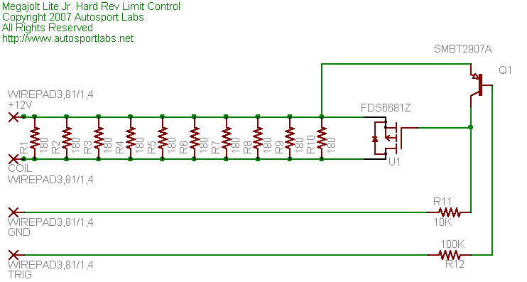
Under normal operation U1 conducts and passes full current to the coil pack. When triggered, the Mosfet is turned off and current flows through the resistor array, reducing current in the coil pack primary windings and thereby suppressing spark output.
The Mosfet transistor U1 was selected for it's extremely low on-resistance (0.0038 Ohms). This performance gives it a high 20A current rating in a tiny package without requiring a large heat sink.
Board
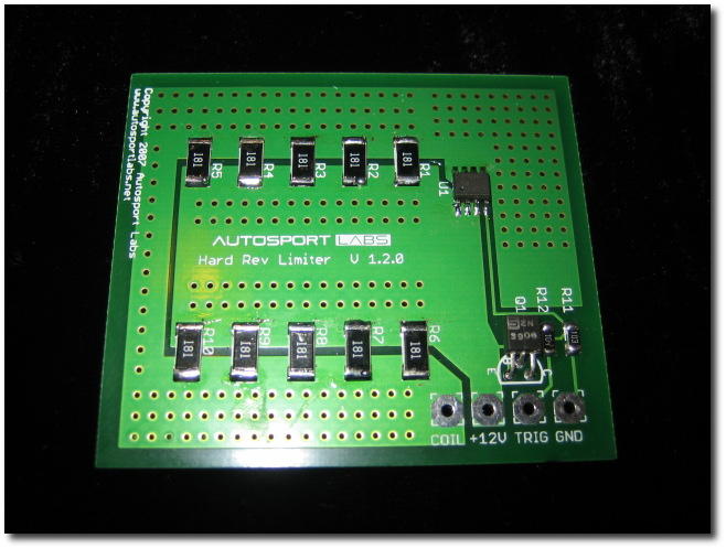
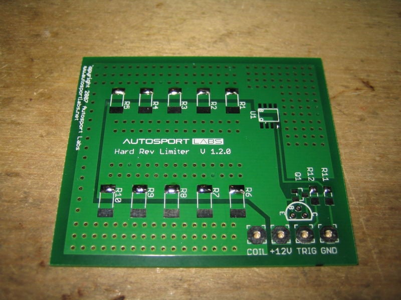
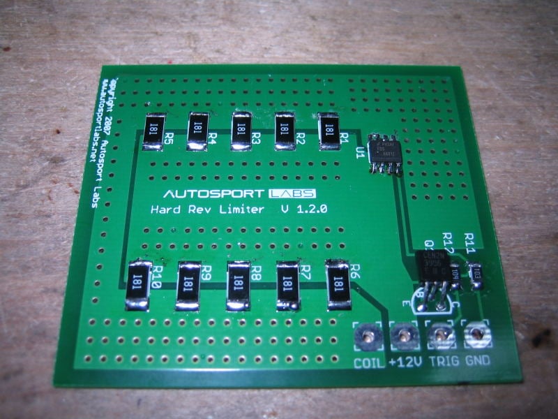
The module is housed on a small, low profile board with the exclusive use of rugged surface mount components. The board is sized to slide into one of the available slots of the MJLJ enclosure; or you can mount it to suit your application.
Assembling the kit
Tools you will need
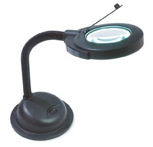
This project makes exclusive use of surface mount components. While SMT assembly may seem daunting to some electronic hobbyists, the use of appropriate tools, techniques and using reasonably sized components, like the 1206 SMT package, can make surface mount easy enough after a bit of practice. Below are pictures some of the essential tools you'll need for this project.
- A fine-tipped, low wattage soldering iron is necessary for precision work.
- Probably the best tool - a cross-action set of tweezers. This tool is normally closed, allowing you to hold parts with a relaxed grip and reduced tremors.
- Solder wick. Too much solder and you'll create ugly blobs and solder spikes. use this to clean up your joints by drawing away excess solder.
- A magnifying glass, preferably illuminated, is useful for identifying package markings and inspecting solder joints.
Parts Inventory
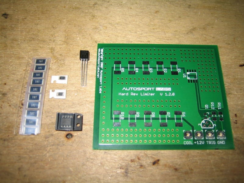
| Part Number | Description |
|---|---|
| U1 | FDS6681Z P-Channel Mosfet |
| R1-R10 | 180 ohm, 1W SMT 2412 |
| Q1 | SMBT2907A PNP transistor |
| R11 | 10K 1206 SMT |
| R12 | 100K 1206 SMT |
Surface mount soldering
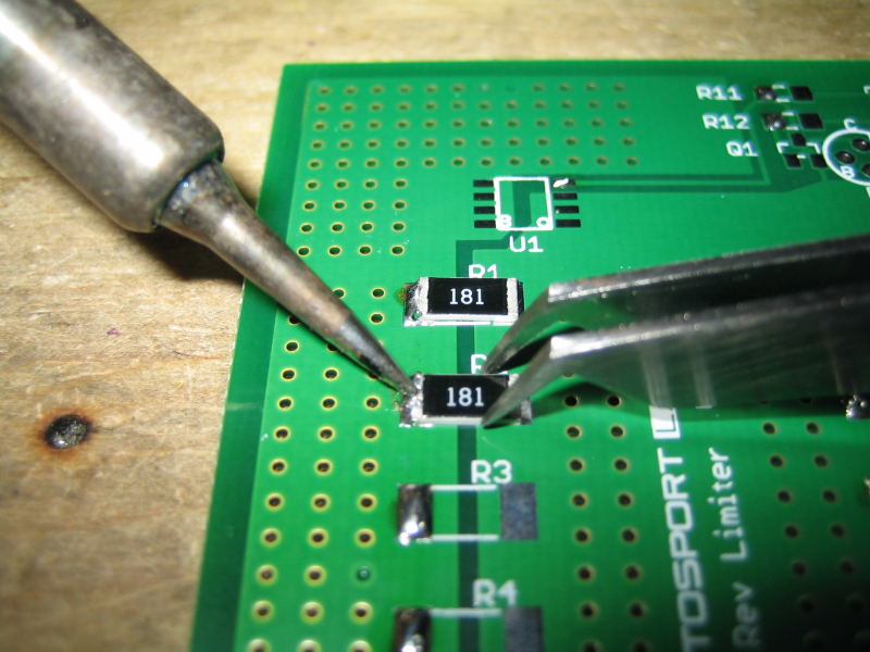
Soldering lead-less surface mount components usually involves tacking one lead down to the board to fix it in place and then working on the remaining leads. With the smaller components, be careful to not apply excessive heat- just enough is needed to flow the solder into the joint. Excessive heat, at minimum, will cause small parts to slide off the pads, and at worst, can destroy them.
Installing the parts
Preparing the solder pads
Start by adding a small amount of solder to one pad of each component. Start with the power resistors, R1 - R10.
Again, only apply solder to one pad- Do not apply solder to both pads of the part. If you do, use solder wick to remove the blob of solder from the other pad. Solder blobs on both pads makes it very hard to get the part flat onto the board when soldering.
Next, apply a small solder blob to one of the pads for the transistor Q1, Mosfet U1, and R11 and R12.
For U1, best is to apply the solder to the pin closest to the Q1 label.
Installing the power resistors
Once the pads are prepped with solder, pick up one of the resistors with your tweezers and position it next to the solder blob. Using the soldering iron, heat the blob until melting and then slide the resistor so that it is centered and square on the pads. Repeat for the remaining resistors.
After all of the resistors are tacked into place, solder the opposite pads of each resistor. Realize that due to the large amount of copper it may take extra time to heat the pad. 5 full seconds with a fine tip soldering iron should be enough to heat the pad and resistor before applying solder. Pay close attention to verify the solder flows under and around the resistor chip.
Installing supporting components
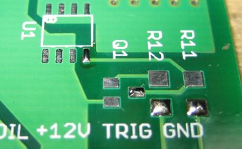
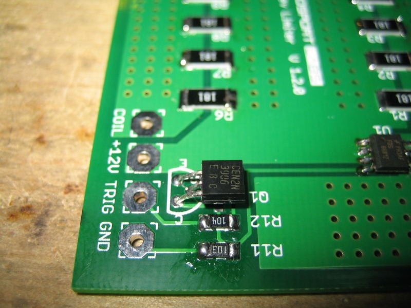
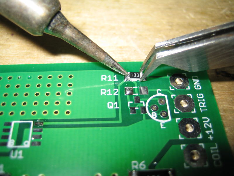
Install Q1. For kit builders, a 2N3906 PNP transistor has been supplied for ease of assembly. Insert Q1 with the orientation shown, leaving enough lead length to fold the transistor flat against the board- this will be needed to ensure low profile installations.
Using the same technique as the power resistors, install the 10K resistor for R11 and the 100K resistor for R12. Solder the other side of the resistors.
Be careful - do not apply heat for too long on the other side of the resistor or the first solder pad will melt, sliding the part off of the pad- requiring you to start over!
Installing power transistor
Caution: U1 is a static sensitive device- employ appropriate ESD precautions, especially when working in a extremely dry or static prone environment.
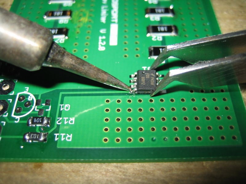
The dot on U1's package denotes pin 1, which must be in the lower left hand side with the board oriented where the silkscreen writing is readable.
Install U1 by centering it over the pads and melting the solder blob previously prepared, tacking the part in place. Move to the diagonal opposite pin, tack that in place and then work on the remaining pins.
Note: Due to the large amount of copper underneath the pins of U1, it will take extra long to get the pins to soldering temperature- so be patient when soldering here.
Note 2: soldering U1 offers the rare opportunity to have solder bridges without consequences! U1 pins 5-8 are all connected together, in addition to pins 1-3. Solder bridges are OK on these connected pins- just be sure to not bridge Pin 4 (Gate), which connects to R11 and Q1.
Final Inspection
Inspect the board carefully to make sure all pads are properly soldered. The solder joints should be bright and slightly domed. Pay particular attention to U1: Ensure pin 4 (Gate) does not have any solder bridges.
Installing the Hard Rev Limiter
Physical Installation
It's up to the user to determine how to install the rev limiter module. Following are a couple of possible installation options.
Since the resistor array generates heat when rev-limiting is active, ambient temperature and air flow across the module will affect the duty-cycle of the unit- meaning how often and long you'll be able to be 'on' the rev-limiter.
TODO: add duty-cycle testing results
Freestanding installation
Depending on your engine's wiring harness layout, it may make sense to install the module free standing, mounted to a surface, or installed into it's own enclosure.
Integrating into the MJLJ enclosure
The Rev Limiter board is sized to fit both the V3 and V4 controller. Rotate the controller to fit the enclosure rails.
V4 Controller
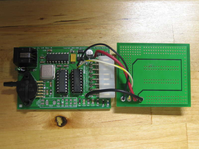
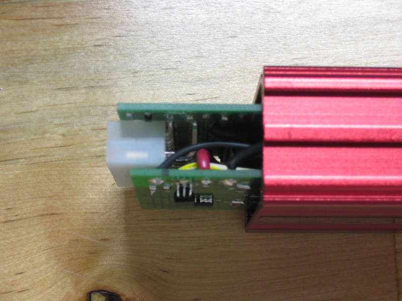
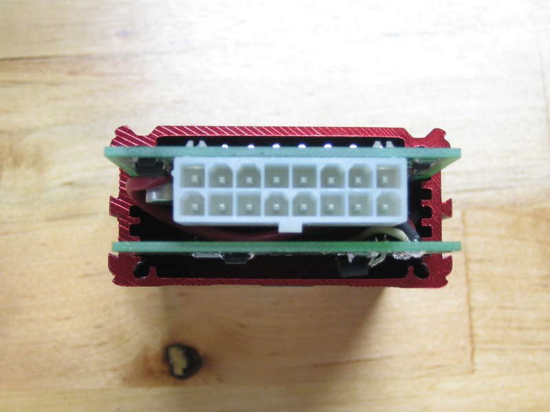
Wire the Rev Limiter board to the +12V, Coil Power, Trigger and ground pads on the V4 board. Use 14 gauge wire for the +12V and Coil Power pads and 22-18 gauge wire for trigger and ground.
Refer to the following for wiring and board installation:
Slide the board into one of the slots above the main board.
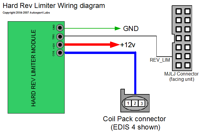
External Wiring Diagram
With this approach, several wiring possibilities exist:
- Cut a hole in the end plate, and route all wires outside the case, looping back to the MJLJ wiring harness plug;
- Cut a hole in the end plate, externally expose the +12v and coil pack connectors, but connect the ground and trigger with jumpers to the inside of the case.
- Most ambitious: wire everything internally:
- Jumper GND connection to MJLJ GND;
- Jumper +12V connection to MJLJ +12V (14 gauge wire);
- Use a thicker gauge wire (14 gauge) for MJLJ +12V power, if necessary, as the +12v supply will supply current to the coil in addition to powering the MJLJ electronics;
- Jumper trigger input to REV_LIMIT output on MJLJ board;
- Cut the REV_LIMIT trace on the MJLJ board running from the ULN2003 to the REV_LIMIT connector pin. The REV_LIMIT pin will now be the new COIL power supply..
- Connect the Rev limit COIL output to REV_LIMIT pin on MJLJ connector.

