Sequential shift light array: Difference between revisions
m (content placeholder!) |
(added panel drill template) |
||
| (2 intermediate revisions by the same user not shown) | |||
| Line 2: | Line 2: | ||
==Kit assembly== | ==Kit assembly== | ||
<br> | <br> | ||
( | ===Install Resistors=== | ||
*'''R1,R2''' Install included 100 ohm resistor (marked 101) | |||
[[Image:ssl_r1_r2.jpg]] | |||
<br><br> | |||
*'''R3,R4,R5''' Install included 270 ohm resistor (marked 271) | |||
[[Image:ssl_r3_r4_r5.jpg]] | |||
<br><br> | |||
===Install LEDs=== | |||
Install LEDs so that the flat side on the LED case matches the outline on the board silkscreen. | |||
*'''Cluster A1,A2:''' Install green LEDs for L1 - L8 | |||
*'''Cluster A3,A4:''' Install yellow LEDs for L9 - L16 | |||
*'''Cluster A5:''' Install Red LEDs for L17 - L20 | |||
[[Image:ssl_board_construction.jpg]] | |||
==Wiring== | |||
===Basic Operation=== | |||
Wire pad +12v to ignition switched +12V. | |||
To activate the following clusters: | |||
*'''Cluster 1:''' Connect A1 to ground | |||
*'''Cluster 2:''' Connect A2 to ground | |||
*'''Cluster 3:''' Connect A3 to ground | |||
*'''Cluster 4:''' Connect A4 to ground | |||
*'''Cluster 5:''' Connect A5 to ground | |||
===Integration with the Megajolt Lite Jr.=== | |||
User outputs 1-4 + shift light output can be used to control the sequential shift light. | |||
*'''Cluster 1:''' Connect A1 to MJLJ User Output 1 | |||
*'''Cluster 2:''' Connect A2 to MJLJ User Output 2 | |||
*'''Cluster 3:''' Connect A3 to MJLJ User Output 3 | |||
*'''Cluster 4:''' Connect A4 to MJLJ User Output 4 | |||
*'''Cluster 5:''' Connect A5 to MJLJ Shift Light Output | |||
* For MJLJ wiring, see the Installation guide- [[MJLJ_V4_vehicle_installation_guide#Megajolt_Lite_Jr._Wiring|Wiring]] section. | |||
* For software configuration, see the Operation Guide- [[MJLJ_V4_Operation_Guide#User_Output_Configuration|User output configuration]] section. | |||
===Panel Drill Template=== | |||
Use this image as a drill template if you wish to mount this behind a panel. | |||
<center> | |||
[[Image:ssl_drill_template.png]] | |||
<br> | <br> | ||
200 DPI template | |||
</center> | |||
==Images== | ==Project Images== | ||
[[Image:ssl_illuminated_angle.jpg|320px]] | [[Image:ssl_illuminated_angle.jpg|320px]] | ||
Latest revision as of 07:08, 26 June 2008
Kit assembly
Install Resistors
- R1,R2 Install included 100 ohm resistor (marked 101)
- R3,R4,R5 Install included 270 ohm resistor (marked 271)
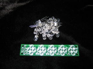
Install LEDs
Install LEDs so that the flat side on the LED case matches the outline on the board silkscreen.
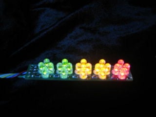
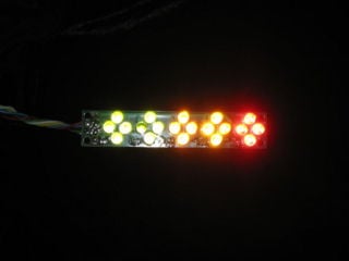
- Cluster A1,A2: Install green LEDs for L1 - L8
- Cluster A3,A4: Install yellow LEDs for L9 - L16
- Cluster A5: Install Red LEDs for L17 - L20
Wiring
Basic Operation
Wire pad +12v to ignition switched +12V.
To activate the following clusters:
- Cluster 1: Connect A1 to ground
- Cluster 2: Connect A2 to ground
- Cluster 3: Connect A3 to ground
- Cluster 4: Connect A4 to ground
- Cluster 5: Connect A5 to ground
Integration with the Megajolt Lite Jr.
User outputs 1-4 + shift light output can be used to control the sequential shift light.
- Cluster 1: Connect A1 to MJLJ User Output 1
- Cluster 2: Connect A2 to MJLJ User Output 2
- Cluster 3: Connect A3 to MJLJ User Output 3
- Cluster 4: Connect A4 to MJLJ User Output 4
- Cluster 5: Connect A5 to MJLJ Shift Light Output
- For MJLJ wiring, see the Installation guide- Wiring section.
- For software configuration, see the Operation Guide- User output configuration section.
Panel Drill Template
Use this image as a drill template if you wish to mount this behind a panel.


