RCP stimulator: Difference between revisions
| (7 intermediate revisions by the same user not shown) | |||
| Line 8: | Line 8: | ||
Notes: | Notes: | ||
* You can provide power + ground to RCP using the 12v and Ground outputs on the Stimulator. The power and ground on the RCP will not provide power or ground to the Stimulator. The Stimulator needs its own power. | * You can provide power + ground to RCP using the 12v and Ground outputs on the Stimulator. The power and ground on the RCP will not provide power or ground to the Stimulator. The Stimulator needs its own power. | ||
* The power plug is a 5.5x2.5mm. | * The power plug is a 5.5x2.5mm. Certain 5.5x2.1 may also work. | ||
* You can use a [https://amzn.to/2XwSF1w 5V USB adapter] to power it, however it | * You can use a [https://amzn.to/2XwSF1w 5V USB adapter] to power it, however it may not have enough power to also power the RCP. If using 5V USB to power the Stimulator, you will also need to plug the RCP into USB to power the RCP seperately. | ||
* Here is a cheap 5V USB power adapter that will work with the Stimulator. https://amzn.to/2XwSF1w | * Here is a cheap 5V USB power adapter that will work with the Stimulator. https://amzn.to/2XwSF1w | ||
* RCP MK3 plug is a standard 24 pin Molex ATX computer power plug. You can buy an [https://amzn.to/2XBLSno ATX extension cable for $7]. Cut the cables in half and wire the male end to the Stimulator terminal blocks. You could then use the female end to make an adapter to go from RCP MK3 molex to [https://www.autosportlabs.com/product/20-pin-pluggable-terminal-block/ RCP MK2 20 pin terminal block]. This would allow you to use your Stimulator for both MK3 and MK2 RCP's. | * RCP MK3 plug is a standard 24 pin Molex ATX computer power plug. You can buy an [https://amzn.to/2XBLSno ATX extension cable for $7]. Cut the cables in half and wire the male end to the Stimulator terminal blocks. You could then use the female end to make an adapter to go from RCP MK3 molex to [https://www.autosportlabs.com/product/20-pin-pluggable-terminal-block/ RCP MK2 20 pin terminal block]. This would allow you to use your Stimulator for both MK3 and MK2 RCP's. | ||
[[file:MK3toMK2Adapter.jpg|500px]] | |||
* Do not connect the stimulator's 5v output to the 5v VREF output on RaceCapture/Pro; it is only provided for reference. | * Do not connect the stimulator's 5v output to the 5v VREF output on RaceCapture/Pro; it is only provided for reference. | ||
* The AUX TX/ RX line needs to be connected in the following fashion so data can flow correctly: | * The AUX TX/ RX line needs to be connected in the following fashion so data can flow correctly: | ||
| Line 17: | Line 18: | ||
** Stimulator AUX_RX -> RCP AUX_TX | ** Stimulator AUX_RX -> RCP AUX_TX | ||
* CAN bus 1 and 2 are bridged together; you can disable this by breaking the PCB jumpers on the bottom side of the board, near terminal block, using a razor knife or a very small screwdriver | * CAN bus 1 and 2 are bridged together; you can disable this by breaking the PCB jumpers on the bottom side of the board, near terminal block, using a razor knife or a very small screwdriver | ||
* You can download a preset config file for the Stimulator here: [[file:RCP_Stimulator_MK3.zip]] | |||
* The blue 5 pin female and 6 pin male headers are for programming the microcontroller. The button between them is for putting the microcontroller into bootloader mode. Do not use these unless instructed to. | |||
==Analog outputs== | ==Analog outputs== | ||
| Line 22: | Line 25: | ||
==RPM/Pulse outputs== | ==RPM/Pulse outputs== | ||
4 Pulse outputs are provided to stimulate up to 4 RPM/Pulse inputs. The pulse outputs work well for simulating a low to high RPM range using the following RPM channel settings: | 4 Pulse outputs are provided to stimulate up to 4 RPM/Pulse inputs. The pulse outputs work well for simulating a low (420) to high (10,000) RPM range using the following RPM channel settings: | ||
* 1 pulse per revolution | * 1 pulse per revolution | ||
* Medium Speed timer channel | * Medium Speed timer channel | ||
| Line 61: | Line 64: | ||
==CAN bus output== | ==CAN bus output== | ||
4 knobs control the value of 4 CAN channels. These channels are broadcast on CAN ID 276: | 4 knobs control the value of 4 CAN channels. These channels are broadcast on CAN ID 276. The baud rate is 500k: | ||
* Channel 1: Offset 0, length 2 | * Channel 1: Offset 0, length 2 | ||
Latest revision as of 01:58, 16 July 2019
Connections
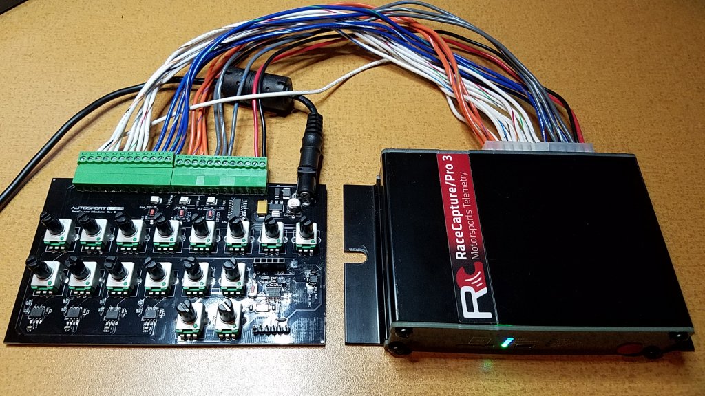
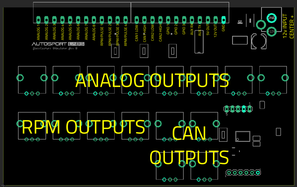
Connect the stimulator to the RaceCapture/Pro inputs using the following diagram.
Notes:
- You can provide power + ground to RCP using the 12v and Ground outputs on the Stimulator. The power and ground on the RCP will not provide power or ground to the Stimulator. The Stimulator needs its own power.
- The power plug is a 5.5x2.5mm. Certain 5.5x2.1 may also work.
- You can use a 5V USB adapter to power it, however it may not have enough power to also power the RCP. If using 5V USB to power the Stimulator, you will also need to plug the RCP into USB to power the RCP seperately.
- Here is a cheap 5V USB power adapter that will work with the Stimulator. https://amzn.to/2XwSF1w
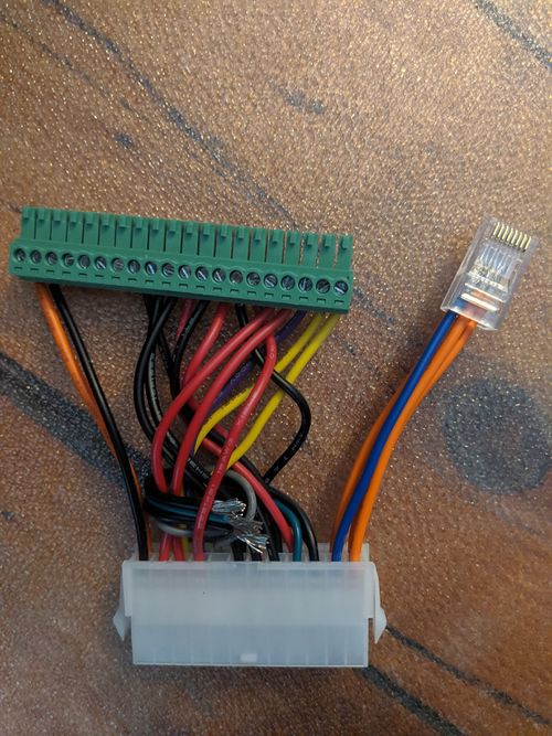
- RCP MK3 plug is a standard 24 pin Molex ATX computer power plug. You can buy an ATX extension cable for $7. Cut the cables in half and wire the male end to the Stimulator terminal blocks. You could then use the female end to make an adapter to go from RCP MK3 molex to RCP MK2 20 pin terminal block. This would allow you to use your Stimulator for both MK3 and MK2 RCP's.
- Do not connect the stimulator's 5v output to the 5v VREF output on RaceCapture/Pro; it is only provided for reference.
- The AUX TX/ RX line needs to be connected in the following fashion so data can flow correctly:
- Stimulator AUX_TX -> RCP AUX_RX
- Stimulator AUX_RX -> RCP AUX_TX
- CAN bus 1 and 2 are bridged together; you can disable this by breaking the PCB jumpers on the bottom side of the board, near terminal block, using a razor knife or a very small screwdriver
- You can download a preset config file for the Stimulator here: File:RCP Stimulator MK3.zip
- The blue 5 pin female and 6 pin male headers are for programming the microcontroller. The button between them is for putting the microcontroller into bootloader mode. Do not use these unless instructed to.
Analog outputs
8 Analog outputs are provided to simulate the respective sensor inputs. The 8 channels are the knobs in the upper row.
RPM/Pulse outputs
4 Pulse outputs are provided to stimulate up to 4 RPM/Pulse inputs. The pulse outputs work well for simulating a low (420) to high (10,000) RPM range using the following RPM channel settings:
- 1 pulse per revolution
- Medium Speed timer channel
- RPM mode
GPIO
The respective LEDs will illuminate when the GPIO port is active Low (connected to ground) - either by pressing the switch, or if activated by RaceCapture when the GPIO is in output mode.
Input Mode
Configure your GPIOs under Setup/Digital In/Out for input mode, and then configure a gauge on the dash to observe the state.
When the Button is pressed, the value will read as '1', indicating the GPIO is connected to ground (Active Low).
Output mode and Demo script
Run this script to demonstrate the GPIOs in output mode.
- Note Ensure the GPIO ports are in output mode under RaceCapture Setup / Digital In/Out.
--Demo script for toggling LEDs on stimulator board
--GPIOs must be set for output mode in RaceCapture Setup

setTickRate(1)

count = 0

function onTick()
  --toggle LEDs
  local state = count % 2
  setGpio(0, state == 0)
  setGpio(1, state == 0)
  setGpio(2, state == 0)
  count = count + 1

end
CAN bus output
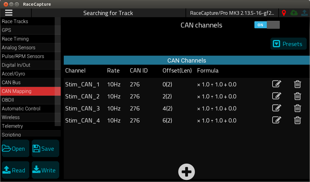
4 knobs control the value of 4 CAN channels. These channels are broadcast on CAN ID 276. The baud rate is 500k:
- Channel 1: Offset 0, length 2
- Channel 2: Offset 2, length 2
- Channel 3: Offset 4, length 2
- Channel 4: Offset 6, length 2
The CAN data is broadcast as a raw value between 0-10000 and can be scaled further using the CAN channel mapping.
Note:
- CAN bus 1 and 2 are bridged together; you can disable this by breaking the PCB jumpers on the bottom side of the board, near terminal block, using a razor knife or a very small screwdriver
RS232 serial output (AUX_TX / AUX_RX)
The stimulator will output the current Analog channel data on the serial port, which can be read by the Aux Serial input of RaceCapture/Pro.
When wiring, ensure the connections are made as per the following:
- Stimulator AUX_TX -> RCP AUX_RX
- Stimulator AUX_RX -> RCP AUX_TX
Baud Rate
Baud rate is 115200, 8N1
Format
The output format is CSV with the following columns:
- Timestamp in milliseconds
- Channel 1 value (0-10000)
- Channel 2 value (0-10000)
- Channel 3 value (0-10000)
- Channel 4 value (0-10000)
- Value echoed back from received data
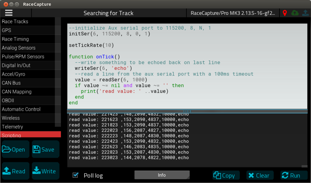
Example Lua script to read serial data
--initialize Aux serial port to 115200, 8, N, 1
initSer(6, 115200, 8, 0, 1)

setTickRate(10)

function onTick()
  --write something to be echoed back
  writeSer(6, 'echo')
  --read a line from the aux serial port with a 100ms timeout
  value = readSer(6, 1000)
  if value ~= nil and value ~= '' then
    print('read value: ' ..value)
  end
end
Example Raw output stream from Stimulator
352023 ,0,0,0,0,echo
352223 ,0,0,0,0,echo
352423 ,0,0,0,0,echo
352623 ,0,0,0,0,echo
352823 ,0,0,0,0,echo
353023 ,0,0,0,0,echo
353223 ,275,0,0,0,echo
353423 ,1680,0,0,0,echo
353623 ,1680,0,0,0,echo
353823 ,1680,0,0,0,echo
354023 ,1672,0,0,0,echo
354223 ,1697,1181,0,0,echo
354423 ,1699,2666,0,0,echo
354623 ,1704,2649,0,0,echo
354823 ,1706,2656,0,0,echo
355023 ,1692,2647,0,0,echo
355223 ,1728,4554,0,0,echo
355423 ,1724,4595,0,0,echo
355623 ,1741,4588,0,0,echo
355823 ,1753,4590,1199,0,echo
356023 ,1750,4588,1323,0,echo
356223 ,1755,4588,4730,0,echo
356423 ,1750,4588,4984,0,echo
356623 ,1758,4586,4981,0,echo
356823 ,1750,4583,4959,1299,echo
357023 ,1758,4586,4964,4129,echo
357223 ,1758,4588,4947,4473,echo
357423 ,1753,4586,4957,5269,echo
357623 ,1753,4586,4957,5768,echo

