Gps-bolt-on: Difference between revisions
| Line 16: | Line 16: | ||
* Multipath detection and suppression | * Multipath detection and suppression | ||
* Accuracy 2.5m CEP | * Accuracy 2.5m CEP | ||
* Maximum update rate | * Maximum update rate 50 Hz | ||
* Tracking current ~33mA | * Tracking current ~33mA | ||
Revision as of 14:15, 21 August 2024
GPS Bolt-on
Introduction
A GPS module includes a small processor and antenna that receives signals directly from satellites. These signals are sent through specific RF (radio frequency) channels and include timestamps along with other relevant data. When the module's antenna detects signals from at least four satellites, it can accurately determine its position and the precise time. This capability is crucial for various applications, such as navigation, tracking, and timing.
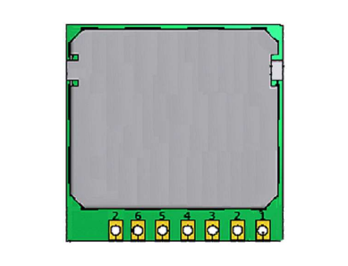
The GPS module that is used in the bolt-on is SUP500F. The SUP500F is a specialized GPS receiver module designed to be easily integrated into various OEM products. This module offers a compact, all-in-one solution that minimizes development risk and simplifies system integration.
Features
- 65 Channel GPS L1 C/A Code
- Perform 8 million time-frequency hypothesis testing per second
- Open sky hot start 1 sec
- Open sky cold start 29 sec
- Signal detection is better than -161dBm
- Multipath detection and suppression
- Accuracy 2.5m CEP
- Maximum update rate 50 Hz
- Tracking current ~33mA
Optional Features
The Board supports an optional CR1220 battery port to help the GPS module warm up and acquire satellites faster. If the battery is omitted, it will always start cold.
These features make the SUP500F ideal for applications that demand high performance, and low power consumption which can be personal navigation devices, asset tracking systems, and vehicle navigation products.
Getting Started
Components
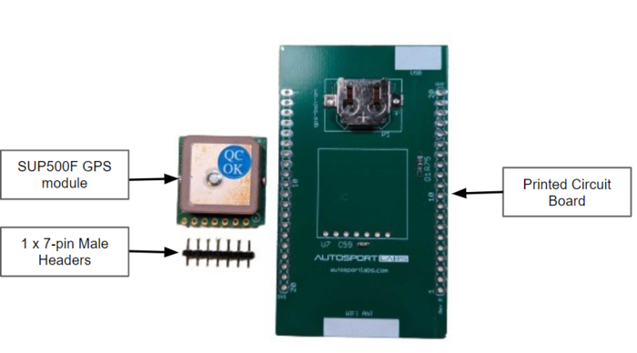
The bolt-on assembly includes
- SUP500F GPS module
- Printed Circuit Board
- 1 x 7-pin Male Headers
Hardware Connection
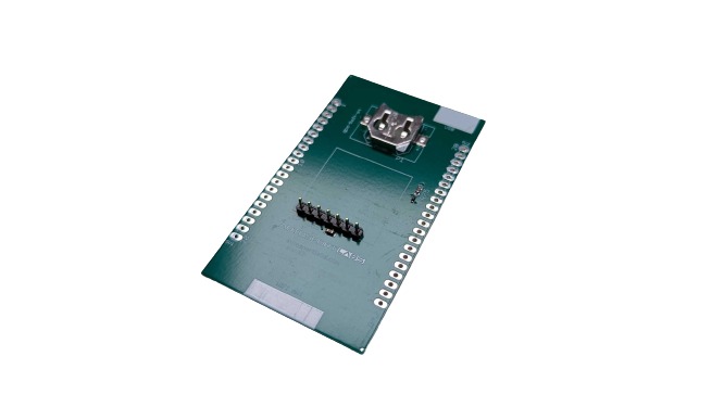
To integrate the GPS module, a 7-pin header (included with the kit) must be soldered to both the GPS module and the PCB.
Additionally, the assembly requires 2 x 20-pin headers to be soldered onto the PCB, providing the necessary connections.
These headers are available separately from a variety of sources (male / female) Amazon | Ebay
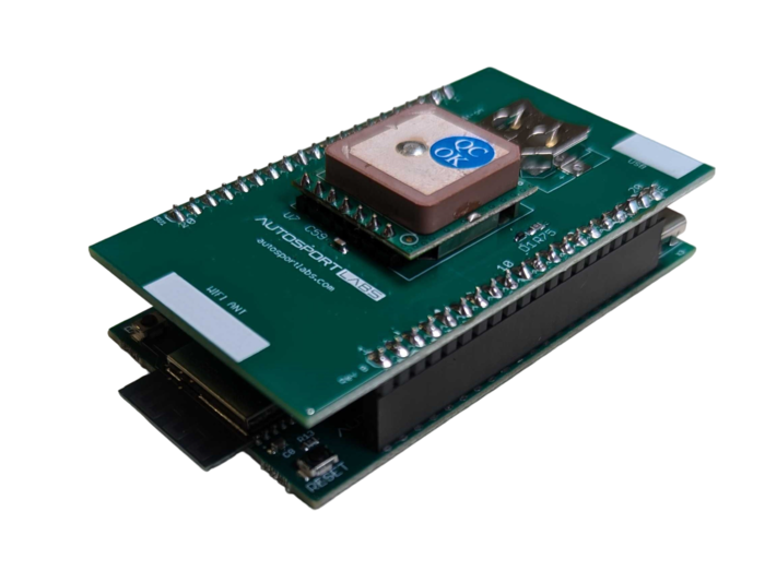
when stacking the GPS bolt-on onto the ESP32 CAN X2 module, ensure that the icons on the boards align, particularly the WiFi antenna and USB positions, to maintain proper functionality and connectivity.
Block diagram, Pin description, and Connections
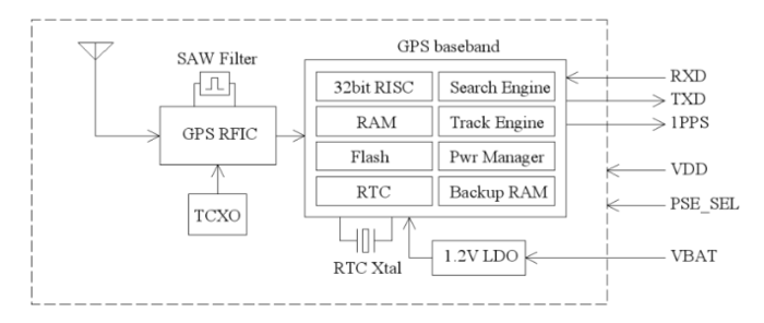
Block Diagram
The block diagram is given in the image below.
Pin Description
The pun description for the SUP500F GPS module is given in the table below.
| Pin No. | Name | Description |
|---|---|---|
| 1 | RXD | UART input, 3V LVTTL |
| 2 | TXD | UART output, 3V LVTTL |
| 3 | GND | System ground |
| 4 | VDD | Main 3.0V ~ 5.5V supply input |
| 5 | VBAT | Backup supply voltage for RTC and SRAM, 1.5V ~ 5.5V Can connect to VDD |
| 6 | P1PS | 1 pulse per second time mark output |
| 7 | PSE_SEL | Search Engine Mode select 1: Low power acquisition mode (default), acquisition current ~55mA 0: Enhanced acquisition mode, acquisition current ~75mA |
Connections
The connection details of the GPS Bolt-on are given in the table below.
| Gps Pin | SV1 | GPIO |
|---|---|---|
| Rx | pin 17 | GPIO40 |
| Tx | pin 18 | GPIO41 |
| P1PPS | pin 16 | GPIO39 |
| PSE_SEL | pin 11 | GPIO45 |
Demo Code
Access the source code repository through the provided link.

