MJLJ V3 vehicle installation guide: Difference between revisions
No edit summary |
(→EDIS installation: initial flesh-out of EDIS installation) |
||
| Line 1: | Line 1: | ||
==EDIS installation== | ==EDIS installation== | ||
==Timing wheel and sensor installation== | |||
The Ford EDIS ignition module is designed to work with a 36 tooth wheel, with 1 missing tooth to act as a synchronization reference for engine Top Dead Center. | |||
When mounting the sensor wheel the EDIS module requires specific positioning of the sensor relative to the missing tooth, ''while the engine is at Top Dead Center''. The following table defines the sensor position relative to the missing tooth for 4,6 and 8 cylinder EDIS modules. | |||
<center> | <center> | ||
{| border = 1 | |||
|+ Sensor Position | |||
|- bgcolor=grey | |||
!Type!!Degrees BTDC | |||
|- | |||
|EDIS-4||90 | |||
|- | |||
|EDIS-6||60 | |||
|- | |||
|EDIS-8||50 | |||
|} | |||
</center> | </center> | ||
With the Engine at TDC for cylinder #1, the sensor should be positioned 'N' degrees before the missing tooth. Make sure you take into account the rotation of the engine: clockwise or counter-clockwise, when determining your sensor mounting. | |||
The following graphic illustrates how the sensor position and missing tooth can vary relative to engine TDC- regardless of where the sensor is mounted, the missing tooth must be positioned accordingly. | |||
<center> | <center> | ||
[[Image: | [[Image:edis_wheel.gif]]<br/> | ||
'''''Shown: Relationship between engine Top Dead Center and sensor positioning. Wherever you place the sensor, the distance from the missing tooth must remain constant.''''' | |||
</center> | </center> | ||
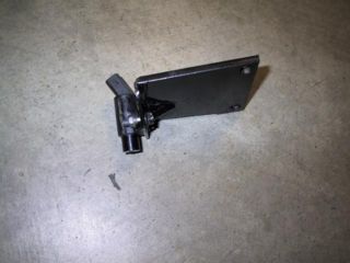
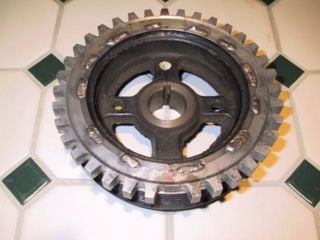
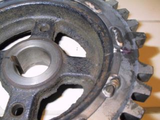
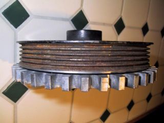
The following photos illustrate an EDIS-4 installation on a Toyota 4AG engine. Notice the thickness of the sensor bracket designed to minimize harmonic vibrations which may affect the sensor signal. The crank pulley was machined down to accommodate the timing wheel from a 1997 Ford Escort, and then tack welded in place. | |||
---- | |||
[[Image:edis_sensor_bracket.jpg|VR Sensor and bracket|320px]] | |||
[[Image:timing_wheel_face.jpg|Machined crank pulley with timing adapted|320px]] | |||
[[Image:timing_wheel_face_close2.jpg|Closeup view of adapted timing wheel|320px]] | |||
[[Image:timing_wheel_end.jpg|Machined pulley with timing wheel adapted|320px]] | |||
[[Image:timing_wheel_mounted.jpg|Modified crank pulley mounted with VR Sensor|320px]] | |||
---- | |||
===EDIS and coil-pack installation=== | ===EDIS and coil-pack installation=== | ||
Revision as of 07:06, 18 March 2007
EDIS installation
Timing wheel and sensor installation
The Ford EDIS ignition module is designed to work with a 36 tooth wheel, with 1 missing tooth to act as a synchronization reference for engine Top Dead Center.
When mounting the sensor wheel the EDIS module requires specific positioning of the sensor relative to the missing tooth, while the engine is at Top Dead Center. The following table defines the sensor position relative to the missing tooth for 4,6 and 8 cylinder EDIS modules.
| Type | Degrees BTDC |
|---|---|
| EDIS-4 | 90 |
| EDIS-6 | 60 |
| EDIS-8 | 50 |
With the Engine at TDC for cylinder #1, the sensor should be positioned 'N' degrees before the missing tooth. Make sure you take into account the rotation of the engine: clockwise or counter-clockwise, when determining your sensor mounting.
The following graphic illustrates how the sensor position and missing tooth can vary relative to engine TDC- regardless of where the sensor is mounted, the missing tooth must be positioned accordingly.
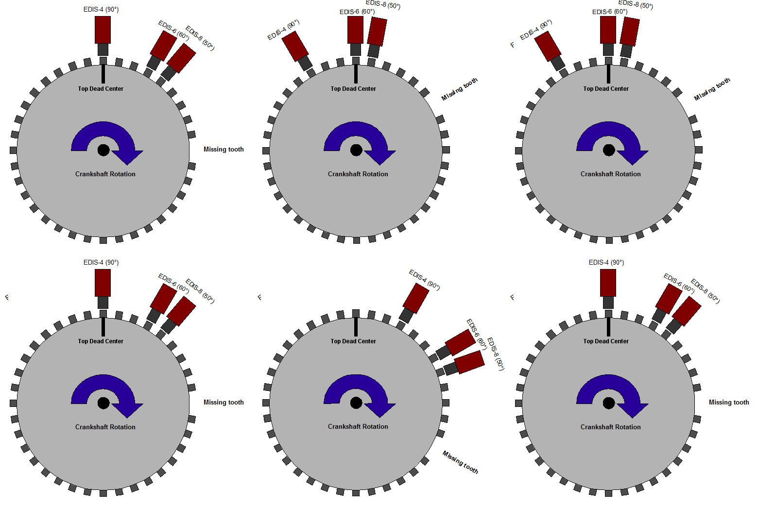
Shown: Relationship between engine Top Dead Center and sensor positioning. Wherever you place the sensor, the distance from the missing tooth must remain constant.
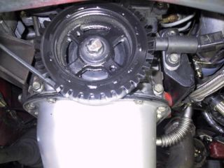
The following photos illustrate an EDIS-4 installation on a Toyota 4AG engine. Notice the thickness of the sensor bracket designed to minimize harmonic vibrations which may affect the sensor signal. The crank pulley was machined down to accommodate the timing wheel from a 1997 Ford Escort, and then tack welded in place.
EDIS and coil-pack installation
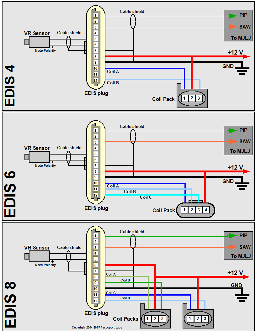
Since the EDIS module can operate the engine by itself in a "limp-home" mode, with the advance fixed at 10 degrees BTDC, it's recommended you install the EDIS module and coil packs first, and then verify your engine runs before wiring in the MJLJ.
Wire up the EDIS module and coil pack(s) using the following diagram, matching your engine type (EDIS 4 = 4 cylinder, EDIS 6 = 6 cylinder, EDIS 8 = 8 cylinder). Engines with 'even-fire' configurations are supported, which represents the vast majority of 4,6, and 8 cylinder engines in production.
Wiring notes and guidelines
- Use shielded cable for the VR Sensor. Be sure to ground the shield as well. A 2 conductor cable with a foil shield works well.
- Note the VR sensor is polarized- you will not get spark from the EDIS module if it is wired backwards. If you don't see spark, try reversing the connection on the VR sensor.
- Minimize supply voltage variances and especially ground loop problems:
- It's strongly recommended you power the EDIS module and MJLJ from the same electrical circuit. Typically this will be +12V switched (Key to "on" position)
- Important! - Ground both the EDIS and MJLJ at the same point on the chassis.

