CoilX: Difference between revisions
| Line 34: | Line 34: | ||
==RaceCapture/Pro Connection== | ==RaceCapture/Pro Connection== | ||
* Connect the CoilX 5v connection to the 5v Vref connection of RaceCapture/Pro. | * Connect the CoilX 5v connection to the 5v Vref connection of RaceCapture/Pro. | ||
** '''Do not exceed 5 volts or damage to module will occur''' | |||
* Connect the CoilX GND connection to the same ground point as RaceCapture/Pro. | * Connect the CoilX GND connection to the same ground point as RaceCapture/Pro. | ||
* Connect the CoilX output signal to one of the Frequency / Pulse inputs channels. | * Connect the CoilX output signal to one of the Frequency / Pulse inputs channels. | ||
Revision as of 17:23, 8 October 2015
Description
Getting a clean RPM signal on an engine is a tricky problem. The signal from the ignition coil is noisy, with multiple signal spikes reaching 400-500 volts. Directly tapping into this signal can cause erratic RPM readings at best, and at worse, damage electronic components.
CoilX is a sensor module that converts the RPM signal from the ignition coil trigger wire into a clean 5v logic-level square wave that can be safely handled by the RaceCapture/Pro Timer / RPM input or other electronic devices.
The module features an optically isolated circuit with additional filtering, to help prevent false triggers.
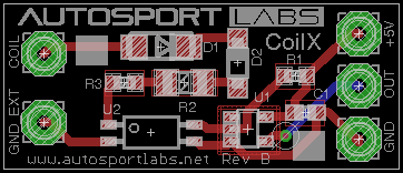
The 1" x 0.5" compact board is designed to be assembled with heat shrink and bundled in-line with your wiring harness.
Wiring Information
Sensor Wiring
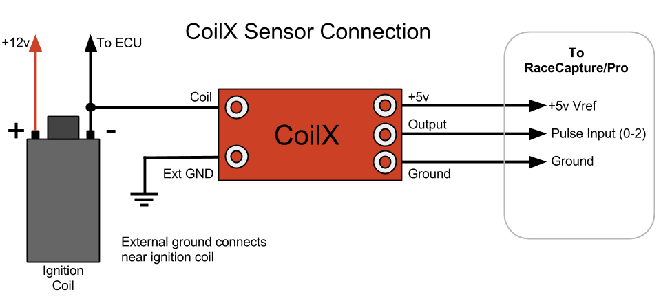
Connect the COIL signal from the CoilX module to the (-) connection of the ignition coil.
- If you have a multiple coil pack system, choose just one coil pack to connect.
- Alternatively, you may be able to tap into the tach signal going to your instrument cluster, but the signal here must be derived from the ignition coil. Newer vehicles (about 2000 and on) may have a low-level signal that may not work with CoilX. Consult your vehicle's documentation or measure the signal with an oscilloscope to verify.
Soldering Wires
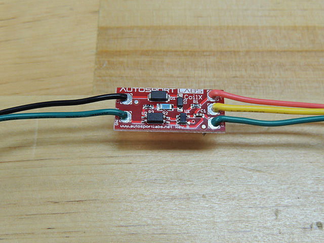
Use 22 gauge wire to solder the connections to the CoilX module.
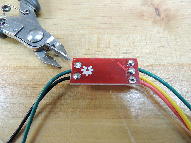
Be sure to clip the soldered wires flush to prevent sharp surfaces.
Label the wires or make note of the colors, then slip the CoilX module into a length of 1" wide heat shrink tubing or wrap in electrical tape to insulate and protect the module. Once it is complete, you can include this assembly with your wiring harness bundle.
RaceCapture/Pro Connection
- Connect the CoilX 5v connection to the 5v Vref connection of RaceCapture/Pro.
- Do not exceed 5 volts or damage to module will occur
- Connect the CoilX GND connection to the same ground point as RaceCapture/Pro.
- Connect the CoilX output signal to one of the Frequency / Pulse inputs channels.
See the Installation Guide for the full wiring diagram.
RaceCapture/Pro Timer/Pulse Channel Configuration
In the Race Capture app, navigate to the pulse input channel configuration page and configure it for your settings.
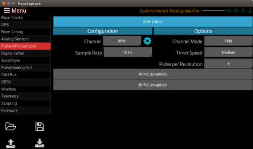
- select RPM for channel Name
- select a sample rate. 10 to 20Hz is usually a good value to start with.
- Select Mode = RPM, Timer Speed = Medium, and pulse per revolution to match the number of cylinders.
- You may need to experiment with this setting to get the correct RPM reading.
PROTIP: With your engine running you can use the channel monitor to view the current live sensor data.
Technical Information
Theory of Operation
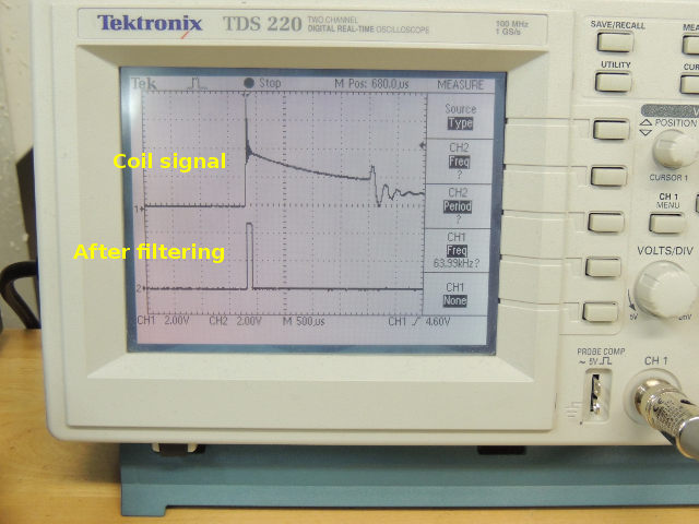
The CoilX module cleans and shapes the noisy 400v ignition flyback signal in the following way:
- The raw ignition signal is passed through a diode to prevent negative voltage transients.
- Then the signal is clipped via a Zener diode so voltages lower than 75v are discarded. This filters out the ringing components of the signal, which is the primary cause of false triggers.
- The clipped signal is passed through an optoisolator via current limiting resistors.
- The optoisolator output is further filtered through a single inverting logic gate using a schmitt trigger filter.
- The filtered / conditioned 0-5v signal is fed into the RaceCapture/Pro timer input channel.

