RacecapturePro MK4 hardware install: Difference between revisions
| Line 40: | Line 40: | ||
# 4-pin female M8 connector for CAN1 and power connections. | # 4-pin female M8 connector for CAN1 and power connections. | ||
<br> | <br> | ||
The detailed explanations of | The detailed explanations of connector pinouts are given below. | ||
Revision as of 20:14, 24 July 2024
Installation
Mounting Orientation
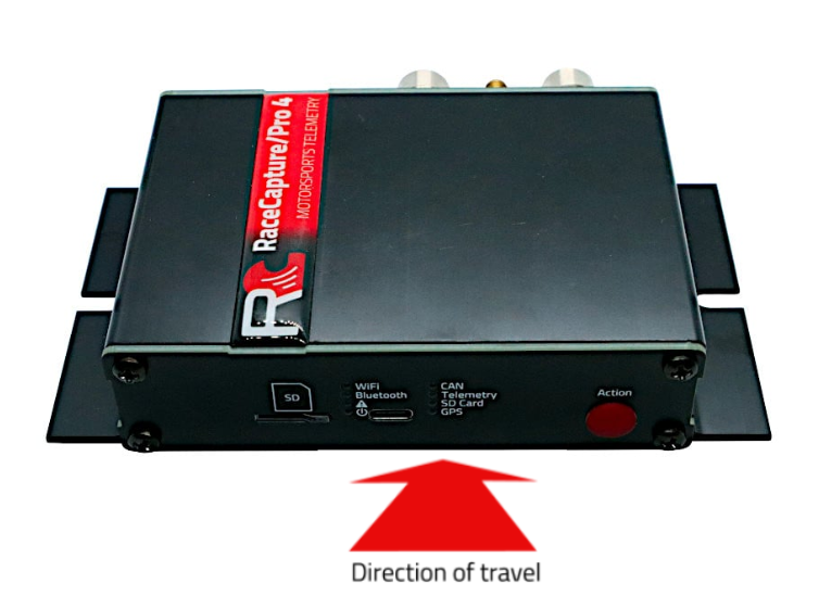
The system can be mounted in various orientations to suit your needs. However, for optimal performance of the accelerometer and gyroscope, it is recommended to mount the system horizontally flat with the indicators facing the driver. After mounting, you can zero out the channels by performing calibration in the Setup section under Accel/Gyro.
Recommended Orientation
Horizontally Flat Indicators facing toward the driver
Alternate Orientations
If needed, the system can also be mounted in alternate orientations. Ensure that any alternate mounting is square to the orientation of the car. Some examples include:
- Upside Down
- Vertical / On Edge
Calibration and Remapping
When an alternate mounting orientation is chosen, it is crucial to remap the accelerometer and gyroscope channels to accurately reflect this change. This can be done in the Setup section under Accel/Gyro.
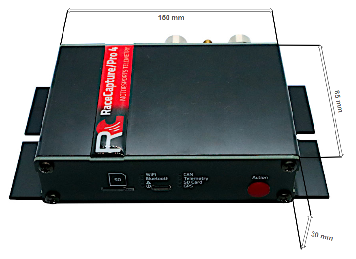
Mounting Dimensions
The mounting dimensions of Racecapture Pro Mk4 are given in the image below.
Connections
The RaceCapturePro MK4 has 5 connectors, detailed as follows from left to right:
- 12-pin female M12 connector for analog input devices.
- SMA connector for GPS antenna connection.
- 12-pin female M12 connector for digital input and RPM sensors.
- 6-pin female M8 connector for CAN1, CAN2, and power connections.
- 4-pin female M8 connector for CAN1 and power connections.
The detailed explanations of connector pinouts are given below.


