Button-bolt-on: Difference between revisions
No edit summary |
|||
| Line 1: | Line 1: | ||
==Introduction== | ==Introduction== | ||
<br> | <br> | ||
[[File:Button Bolt-on white background.jpg| | [[File:Button Bolt-on white background.jpg|600px]] | ||
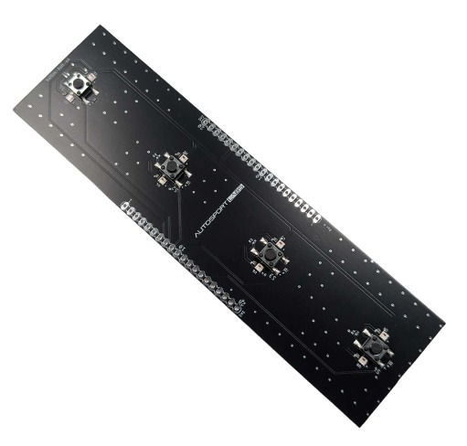
The Button Bolt- | The Button Bolt-On is a modular accessory designed to enhance the functionality of the ESP32-CAN-X2 development board. It integrates tactile push buttons and RGB LEDs for intuitive user interaction and feedback. | ||
==Features== | ==Key Features== | ||
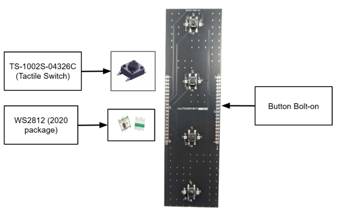
Following are the features of 2 main components TS-1002S-04326C and WS2812 (2020 package) that are used in the Button bolt-on board. | Following are the features of 2 main components TS-1002S-04326C and WS2812 (2020 package) that are used in the Button bolt-on board. | ||
* Four tactile switches with a 6x6 mm footprint and 4.3 mm actuator height, offering reliable operation and minimal accidental presses. | |||
* | * Eight WS2812B 2020 RGB LEDs are strategically positioned around the buttons to provide clear visual feedback for user actions or system states. | ||
* | |||
==Primary Purpose== | |||
* Facilitates CAN-based messaging and local device control. | |||
* | * Enhances user experience with interactive lighting and button functions. | ||
* | |||
[[File:Button Bolt-on getting started.png|700px]] | [[File:Button Bolt-on getting started.png|700px]] | ||
==Applications== | |||
Button bolt-on consists of just a button and an LED so it makes user input functionality simple and efficient. Following are some of the real-world scenarios in which button bolt-ons can fit in perfectly. | |||
===Automotive=== | |||
* Driver selection (e.g., using buttons to identify which driver is using the car). | |||
* Adjust ECU tuning with a press of a button. | |||
== | ===Home Automation=== | ||
* Use buttons to control smart appliances. | |||
* Indicate device states with customizable LED lighting patterns. | |||
===Industrial Use Cases=== | |||
* Trigger remote devices like pumps or fans. | |||
* Use LED signals to display system statuses or warnings | |||
== | ==Getting Started== | ||
===Assembly Instructions=== | |||
== | * Solder two 20-pin headers SV1 and SV2 to the Button Bolt-on PCB. These headers are available separately from a variety of sources (male/female) [https://www.amazon.com/s?k=1x20pin+header+2.54+female Amazon] | [https://www.ebay.com/sch/i.html?_nkw=1x20pin+header+2.54+female+straight Ebay] | ||
* Ensure secure connections between the Bolt-on board and ESP32-CAN-X2 as per the following hardware connection | |||
===Hardware Connections=== | |||
The following are the hardware connections for the Button Bolt-On and the respective ESP32 GPIOs from the ESP32-CAN-X2 board | |||
[[File:Button bolt-on pinout.png|700 px]] | |||
[ | |||
The Following are the ESP32 GPIOs from the ESP32-CAN-X2 board to be used on the button bolt-on | |||
{| class="wikitable" | {| class="wikitable" | ||
|+ | |+ | ||
|- | |- | ||
! SV1 Pins !! ESP32 GPIO !! Purpose | ! SV1 Pins !! ESP32 GPIO !! Purpose | ||
| Line 102: | Line 67: | ||
| 14 || GPIO38 || Connect to Push button S4 | | 14 || GPIO38 || Connect to Push button S4 | ||
|} | |} | ||
===Required Tools and Materials=== | |||
* Button Bolt-On board. | |||
* ESP32-CAN-X2 development board. | |||
* Soldering iron (for assembling headers, if not pre-soldered). | |||
* USB cable Type-C for programming the ESP32. | |||
==Working== | |||
Working of the button bolt-on is simple as mentioned below for both button and LEDs | |||
* Each button can be configured to send unique CAN messages when pressed as well as periodically | |||
* RGB LEDs can provide dynamic feedback based on: | |||
** Button states (e.g., green for "on," red for "off"). | |||
** Incoming CAN messages (e.g., flash when a message is received). | |||
** System diagnostics or statuses. | |||
==Project Examples== | |||
===Project 1: Remote Device Toggle=== | |||
'''Description:'''Use the Bolt-On to send CAN messages to toggle a remote device. | |||
'''Implementation Steps:''' | |||
* Connect the ESP32-CAN-X2 and button bolt-on on top of each other through the connector SV1 and SV2 in the correct configuration. | |||
* Program the ESP32-CAN-X2 board to send a CAN message with the specific data (e.g., "Turn Light On"). based on the button bolt-on input through the S1, S2, S3, and S4 push buttons. | |||
* Program the ESP32-CAN-X2 to use the RGB LEDs on the button bolt-on to flash green on successful transmission and red on unsuccessful transmission of the CAN messages. | |||
===Project 2: Driver Selection System=== | |||
'''Description:''' Configure buttons to assign driver profiles in a vehicle. | |||
'''Implementation Steps:''' | |||
* Connect the ESP32-CAN-X2 and button bolt-on on top of each other through the connector SV1 and SV2 in the correct configuration. | |||
* Map each button to a driver ID (e.g., Driver A = Button 1). | |||
* Use the LEDs to display the selected driver's ID with a specific color pattern. | |||
* Button Status / Driver profiles can be sent periodically or on event bases through CAN bus and remotely so some servers as well. | |||
===Project 3: Status Indicator=== | |||
'''Description:''' Display system health or warnings using the RGB LEDs. | |||
'''Implementation Steps:''' | |||
* Connect the ESP32-CAN-X2 and button bolt-on on top of each other through the connector SV1 and SV2 in the correct configuration. | |||
* Program the LEDs to show green for normal, yellow for warning, and red for critical conditions. | |||
* Update LED states based on incoming CAN messages. | |||
* Reset the LED states via buttons as well. | |||
==Demo Code== | ==Demo Code== | ||
The demo code for the button bolt-on can be found in the following GitHub repo in which the button states are periodically sent over the CAN bus as well as when the button is pressed. | |||
[https://github.com/autosportlabs/ESP32-CAN-X2 Demo Code] | |||
Latest revision as of 05:42, 28 November 2024
Introduction
The Button Bolt-On is a modular accessory designed to enhance the functionality of the ESP32-CAN-X2 development board. It integrates tactile push buttons and RGB LEDs for intuitive user interaction and feedback.
Key Features
Following are the features of 2 main components TS-1002S-04326C and WS2812 (2020 package) that are used in the Button bolt-on board.
- Four tactile switches with a 6x6 mm footprint and 4.3 mm actuator height, offering reliable operation and minimal accidental presses.
- Eight WS2812B 2020 RGB LEDs are strategically positioned around the buttons to provide clear visual feedback for user actions or system states.
Primary Purpose
- Facilitates CAN-based messaging and local device control.
- Enhances user experience with interactive lighting and button functions.
Applications
Button bolt-on consists of just a button and an LED so it makes user input functionality simple and efficient. Following are some of the real-world scenarios in which button bolt-ons can fit in perfectly.
Automotive
- Driver selection (e.g., using buttons to identify which driver is using the car).
- Adjust ECU tuning with a press of a button.
Home Automation
- Use buttons to control smart appliances.
- Indicate device states with customizable LED lighting patterns.
Industrial Use Cases
- Trigger remote devices like pumps or fans.
- Use LED signals to display system statuses or warnings
Getting Started
Assembly Instructions
- Solder two 20-pin headers SV1 and SV2 to the Button Bolt-on PCB. These headers are available separately from a variety of sources (male/female) Amazon | Ebay
- Ensure secure connections between the Bolt-on board and ESP32-CAN-X2 as per the following hardware connection
Hardware Connections
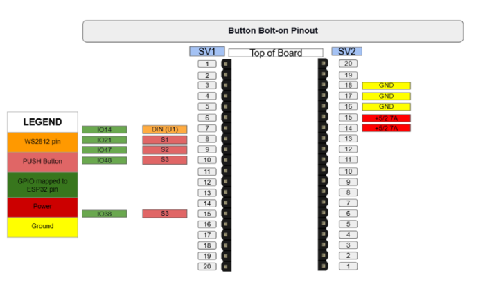
The following are the hardware connections for the Button Bolt-On and the respective ESP32 GPIOs from the ESP32-CAN-X2 board
The Following are the ESP32 GPIOs from the ESP32-CAN-X2 board to be used on the button bolt-on
| SV1 Pins | ESP32 GPIO | Purpose |
|---|---|---|
| 7 | GPIO14 | Connect to DIN of U1 (WS2812) |
| 8 | GPIO21 | Connect to Push button S1 |
| 9 | GPIO47 | Connect to Push button S2 |
| 10 | GPIO48 | Connect to Push button S3 |
| 14 | GPIO38 | Connect to Push button S4 |
Required Tools and Materials
- Button Bolt-On board.
- ESP32-CAN-X2 development board.
- Soldering iron (for assembling headers, if not pre-soldered).
- USB cable Type-C for programming the ESP32.
Working
Working of the button bolt-on is simple as mentioned below for both button and LEDs
- Each button can be configured to send unique CAN messages when pressed as well as periodically
- RGB LEDs can provide dynamic feedback based on:
- Button states (e.g., green for "on," red for "off").
- Incoming CAN messages (e.g., flash when a message is received).
- System diagnostics or statuses.
Project Examples
Project 1: Remote Device Toggle
Description:Use the Bolt-On to send CAN messages to toggle a remote device.
Implementation Steps:
- Connect the ESP32-CAN-X2 and button bolt-on on top of each other through the connector SV1 and SV2 in the correct configuration.
- Program the ESP32-CAN-X2 board to send a CAN message with the specific data (e.g., "Turn Light On"). based on the button bolt-on input through the S1, S2, S3, and S4 push buttons.
- Program the ESP32-CAN-X2 to use the RGB LEDs on the button bolt-on to flash green on successful transmission and red on unsuccessful transmission of the CAN messages.
Project 2: Driver Selection System
Description: Configure buttons to assign driver profiles in a vehicle.
Implementation Steps:
- Connect the ESP32-CAN-X2 and button bolt-on on top of each other through the connector SV1 and SV2 in the correct configuration.
- Map each button to a driver ID (e.g., Driver A = Button 1).
- Use the LEDs to display the selected driver's ID with a specific color pattern.
- Button Status / Driver profiles can be sent periodically or on event bases through CAN bus and remotely so some servers as well.
Project 3: Status Indicator
Description: Display system health or warnings using the RGB LEDs.
Implementation Steps:
- Connect the ESP32-CAN-X2 and button bolt-on on top of each other through the connector SV1 and SV2 in the correct configuration.
- Program the LEDs to show green for normal, yellow for warning, and red for critical conditions.
- Update LED states based on incoming CAN messages.
- Reset the LED states via buttons as well.
Demo Code
The demo code for the button bolt-on can be found in the following GitHub repo in which the button states are periodically sent over the CAN bus as well as when the button is pressed. Demo Code


