IgnitionDrivers: Difference between revisions
No edit summary |
Funky Diver (talk | contribs) m (→Features) |
||
| Line 14: | Line 14: | ||
* 10 pin molex connector for ease of use | * 10 pin molex connector for ease of use | ||
* LEDs indicating driver activity (requires additional drive current of 3-6ma) | * LEDs indicating driver activity (requires additional drive current of 3-6ma) | ||
* Heat-sinking from ''bottom'' of PC board- transistors are soldered down | * Heat-sinking from ''bottom'' of PC board- transistors are soldered down | ||
* 2.48 x 3.14" board sized to fit our compact aluminum enclosure (or other enclosure accepting 2.5" width PC Boards) | * 2.48 x 3.14" board sized to fit our compact aluminum enclosure (or other enclosure accepting 2.5" width PC Boards) | ||
* Metric sizing for board is 63mm x 80mm | |||
==Connector Pinout== | ==Connector Pinout== | ||
Revision as of 10:38, 5 March 2011
Ignition Driver boards
Jolt4 Ignition Driver
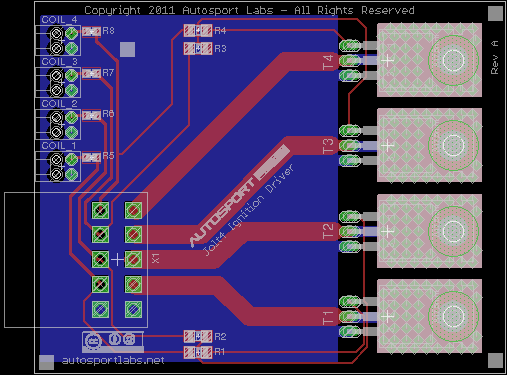
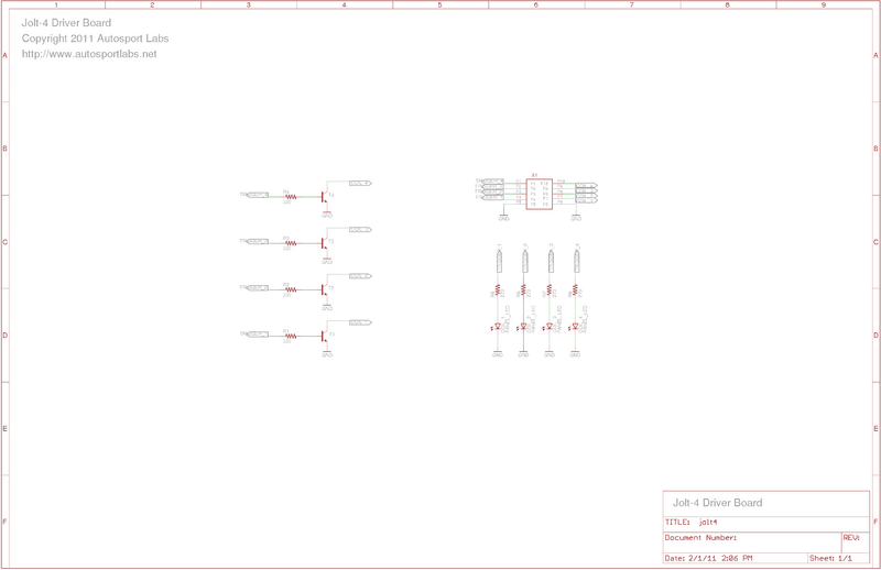
The Jolt4 Ignition Driver board groups together 4 Ignition drive transistors such as the Bosch BIP373 , Fairchild ISL9V3040S3ST and so on.
Features
- Up to 4 ignition drivers supported
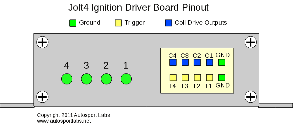
- 10 pin molex connector for ease of use
- LEDs indicating driver activity (requires additional drive current of 3-6ma)
- Heat-sinking from bottom of PC board- transistors are soldered down
- 2.48 x 3.14" board sized to fit our compact aluminum enclosure (or other enclosure accepting 2.5" width PC Boards)
- Metric sizing for board is 63mm x 80mm
Connector Pinout
License
This design is released under the Autosport Labs Creative Commons license


