MJLJ V3 vehicle installation guide: Difference between revisions
(Extra information on EDIS installation and wiring up tachometer) |
|||
| Line 35: | Line 35: | ||
====Using the TACH OUT on the MJLJ==== | ====Using the TACH OUT on the MJLJ==== | ||
Many tachometers can accept the | Many tachometers can accept the signal emitted from the TACH OUT on the MJLJ module. This TACH OUT signal provides a 12V pulse for every ignition event. You may use this to provide the signal to compatible tachometers. | ||
====Tachometers that require a HV kickback pulse==== | ====Tachometers that require a HV kickback pulse==== | ||
Revision as of 19:19, 17 March 2007
Crank trigger wheel and sensor installation
EDIS installation
EDIS and coil-pack installation
Since the EDIS module can operate the engine by itself in a "limp-home" mode, with the advance fixed at 10 degrees BTDC, it's recommended you install the EDIS module and coil packs first, and then verify your engine runs before wiring in the MJLJ.
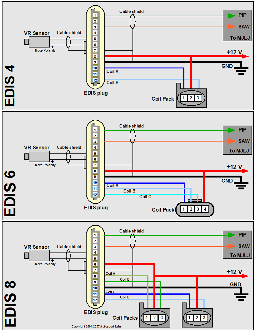
Wire up the EDIS module and coil pack(s) using the following diagram, matching your engine type (EDIS 4 = 4 cylinder, EDIS 6 = 6 cylinder, EDIS 8 = 8 cylinder). Engines with 'even-fire' configurations are supported, which represents the vast majority of 4,6, and 8 cylinder engines in production.
Wiring notes and guidelines
- Use shielded cable for the VR Sensor. Be sure to ground the shield as well. A 2 conductor cable with a foil shield works well.
- Note the VR sensor is polarized- you will not get spark from the EDIS module if it is wired backwards. If you don't see spark, try reversing the connection on the VR sensor.
- Minimize supply voltage variances and especially ground loop problems:
- It's strongly recommended you power the EDIS module and MJLJ from the same electrical circuit. Typically this will be +12V switched (Key to "on" position)
- Important! - Ground both the EDIS and MJLJ at the same point on the chassis.
Installing the MJLJ
MJLJ wiring notes and guidlines
- The MJLJ should be installed inside the passenger compartment. It's not designed to handle the temperature,vibration and moisture extremes of the engine bay.
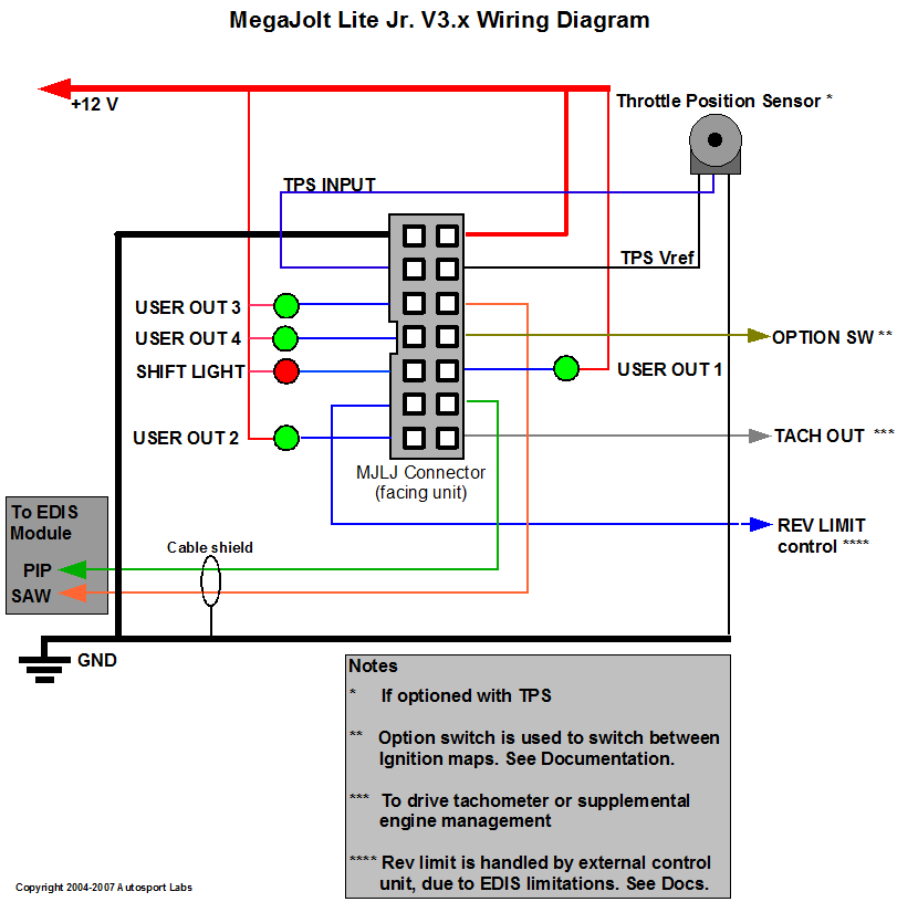
- Use shielded cable for the PIP/SAW signal between the MJLJ and EDSI module. Be sure to ground the shield as well. A 2-conductor cable with a foil sheild works well.
- Use 16 gauge wire for the MJLJ ground connection. 18-20 gauge wiring is fine for power and the other connections.
- For MAP based setups ignore the TPS connections.
Interfacing to Tachometers
Using the TACH OUT on the MJLJ
Many tachometers can accept the signal emitted from the TACH OUT on the MJLJ module. This TACH OUT signal provides a 12V pulse for every ignition event. You may use this to provide the signal to compatible tachometers.
Tachometers that require a HV kickback pulse
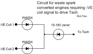
Some OEM-style tachometers detect the RPM signal by sensing the high voltage flyback pulse from the ignition coil. In distributor based setups, there is only one ignition coil to detect this pulse from. With a wasted spark system, this 'signal' is spread across multiple coils. As a result, you will need a way to combine these pulses across multiple coil packs to drive your tachometer.
The following circuit allows the flyback pulse to be detected across individual coil packs while still isolating the coils from each other.

OEM tach adapter circuit
If the above circuit does not work, try omitting the Zener diode.


