BMW E46 CAN: Difference between revisions
(→Manual Setup: fixed water temp, added steering angle) |
|||
| Line 149: | Line 149: | ||
end | end | ||
--E46 TPS, | --E46 TPS, correct your throttle here for true 100% | ||
function e46_tps(value) | function e46_tps(value) | ||
return value * 1. | return value * 1.0 | ||
end | end | ||
Revision as of 17:27, 22 April 2015
Installation
Things you'll need
- Crimp tool
- Wire cutter
- Wire stripper
- Philipps screwdriver
- Multimeter
- 22 gauge solid wire
- RJ 45 (Ethernet) cable, ~6ft
- Shrink tubing (optional, electrical tape will work too, but not look as nice)
- Posi-tap connectors (2) - Do *not* cut the CAN wires during this installation, use wire taps (Posi-taps work very well)
- Butt connectors (2) for 22 gauge wire
- Flashlight
- RaceCapture/Pro with Bluetooth
- Android tablet
- An E46 ;)
Estimated Time
2-3 hours, depending on level of wiring experience. The most time consuming part is splicing the CAN, power and ground wires into the RJ45 cable.
RaceCapture/Pro installation (Race / Spec E46)
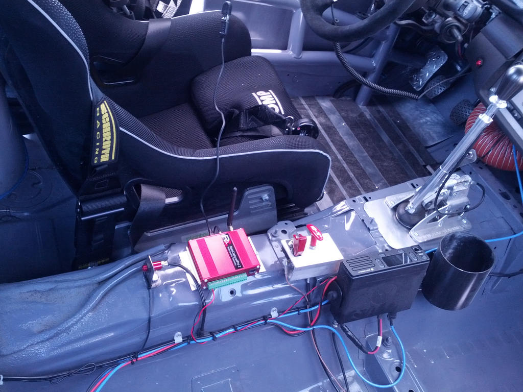
We recommend installing RaceCapture/Pro on the transmission tunnel to the right of the driver's seat. This is near the center of rotation to get the best effect from the on-board IMU (Accelerometer + Gyro)
CAN wires
The CAN+/CAN- wires are located in 2 places: under the driver's side dash above the footrest or in the DME panel. For these instructions it is assumed you are using the wires under the dash.
CAN wire colors are as follows:
- Yellow/Brown = CAN- (low)
- Yellow/Red = CAN+ (high)
They are a twisted pair in or attached to the main wiring harness under the driver's side dash above the dead pedal.
Remove bottom of dash
You will have to remove the panel below the steering wheel via 3 philipps screws, a plastic thumb screw (turn 90 degrees and pull) behind the pedals and a press fit plastic screw on the transmission tunnel (pull the tiny center pin out first, then the larger screw).
Once you have removed the panel you should see a large wiring harness above the dead pedal.
Locate CAN wires
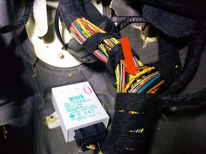
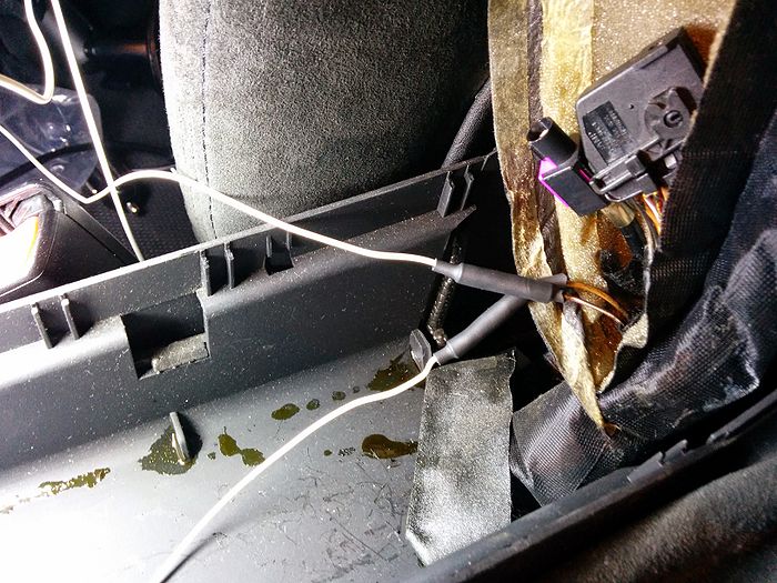
Look for a twisted pair of wires that are Yellow/Brown and Yellow/Red like so:
Those are the 2 wires you need to *tap* into, not cut.
Tapping CAN wires
To tap into the wires, you'll first need to tease them apart because they are very tightly wound. Peel back some of the black cloth tape wrapping the harness and gently pull the wires apart. This may take some time. You'll want to have enough room for 2 fingers in between the wires.
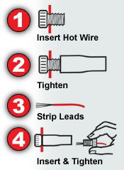
Tapping the wires via Posi-taps (recommended) is easy. Pull the top off the Positap, place the wire in it and tighten. Verify you've tapped the wire by loosening and checking for a hole in the wire.
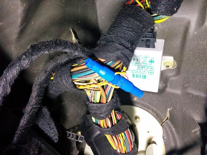
Once you've tapped both it will most likely look like this:
Create CAN wiring for RaceCapture/Pro
Now that you've tapped the CAN wires, cut two 6 foot lengths of solid wire, strip both ends and attach one to CAN+ and CAN-. Make sure to label them or you'll have to keep looking under the dash. Yellow/Brown is CAN- and Yellow/Red is CAN+.
Where you run these two wires is dependent on where RaceCapture/Pro is. You can either run them down the driver's side of the car, next to the dead pedal or find a way to route them into the center dash and out below the CD player/HVAC controls. For these instructions we routed them next to the dead pedal, under the floor mat and taped them onto the transmission tunnel next to the driver hidden away. (Our RaceCapture/Pro was installed on the center rear seat)
Power and ground wiring
Note: You can skip this section if you already have power wired to RaceCapture/Pro and don't want to change it.
Mk1 owners: do not wire in power or ground.
Locate power and ground wires
The easiest to tap and most convenient power wires are under the coin holder in the center armrest. Pull the cup holder and coin holder out. Beneath them will be a cloth/foam wrapper containing a cellular phone connector. It contains 12v switched power and ground. Pull it gently towards the back of the car, then up to get more slack. Pull apart the foam to get to the wires.
The 12v wire is purple/white, ground is brown. *Note*: there is also a tan wire that looks very similar to brown. Compare the two and pick the darker one.
Splice power and ground wires
You can tap these wires if needed, for these instructions we cut them.
Cut 2 pieces of solid wire about 3ft long or appropriate length needed. Cut the 12v and ground wires and connect them to the wires you just made. Tape or add shrink tubing as necessary. Label the wires 12v and ground.
CAN Bus connection
In order for RaceCapture/Pro to read CAN data you need to connect the CAN+/CAN- wires to a RJ45 (ethernet cable).
Cut one end off the RJ45 cable and pull apart all the wires.
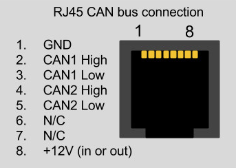
Identify and label the CAN1 High, CAN1 Low, 12v and ground wires via a multimeter. Use the following diagram:
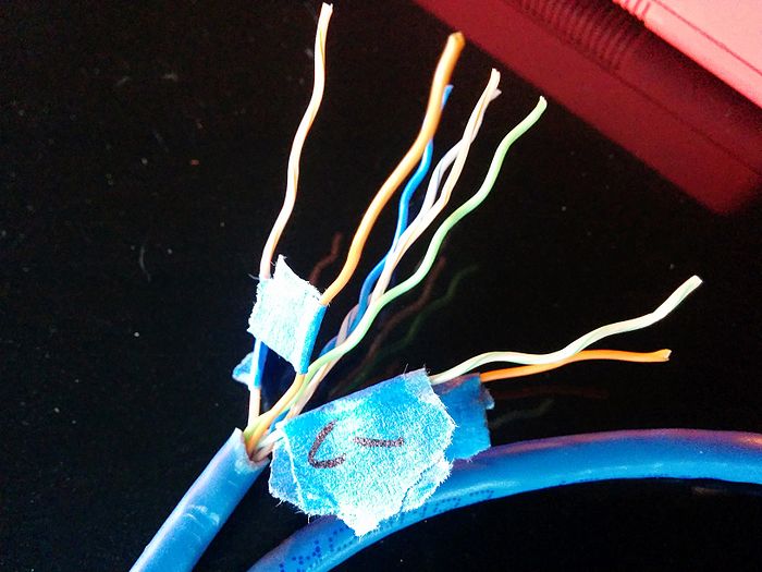
You will end up with something that looks like this:
Once you have identified and labeled the wires, strip them and attach to the CAN wires and power/ground wires from the car. RJ45 wires are very thin, you will want to loop them around the thicker wires and add tape or shrink tubing.
Configure RaceCapture/Pro
Quick Start E46 configuration
This configuration can be imported into your RaceCapture/Pro system to get you started.
Download: E46 CAN starter configuration (right-click, save-as)
To complete your configuration:
- Add your favorite race tracks for automatic detection
- Set your telemetry device id as provided by race-capture.com
Manual Setup
If you already have an existing, customized configuration, follow these steps to add E46 CAN bus integration.
Enable the CAN bus in your RaceCapture/Pro configuration
- Rate is 500kb/s
- Do not enable OBD-II channels.
Add this script to the Scripting section, this will enable Coolant, Oil Temp, Throttle position and brake switch. (More sensors coming soon!)
--This example configured for E46 CAN
-- Automatically starts logging with engine 'on' (RPM triggered)

--how frequently we poll for CAN messages
tickRate = 30
--the CAN baud rate
CAN_baud = 500000
--CAN channel to listen on. 0=first CAN channel, 1=second
CAN_chan = 0
--1 for Big Endian (MSB) mode; 0 for Little Endian mode (LSB)
be_mode = 0

--add your virtual channels here
tpsId = addChannel("TPS", 10, 0, 0, 100, "%")
tempId = addChannel("EngineTemp", 1, 0, 0, 200, 'C')
oilTempId = addChannel("OilTemp", 1, 0, 0, 200, 'C')
rpmId = addChannel("RPM", 10, 0, 0, 10000)
steerId = addChannel("Steering", 10, 0, -360, 360)

function steerFilter(value)
 if value > 32768 - 1 then value = value - 32768 end
 return value
end

--Convert C to F
function toF(value)
 return value * 1.8 + 32
end

--E46 TPS, correct your throttle here for true 100%
function e46_tps(value)
 return value * 1.0
end

--only start logging / telemetry if engine is running
function rpmFilter(value)
 if value > 500 then startLogging() else stopLogging() end
 return value
end

----------------------------------------
--customize here for CAN channel mapping
--format is:
--[CAN Id] = function(data) map_chan(<chan_id>, data, <CAN offset>, <CAN length>, <multiplier>,
--                                   <adder>, [filter])
----------------------------------------
CAN_map = {
[809] = function(data) map_chan(tpsId, data, 5, 1 , 0.392156863, 0, e46_tps) map_chan_le(tempId, data, 1, 1, 0.69202, -48, toF) end,
[1349] = function(data) map_chan(oilTempId, data, 4, 1, 0.8117, -48, toF) end,
[790] = function(data) map_chan(rpmId, data, 2, 2, 0.15625, 0, rpmFilter) end,
[501] = function (data)
    local steer = 0
    if data[2] > 127 then
      steer = -1*(((data[2]-128)*256)+data[1])
    else
      steer = (data[2]*256)+data[1]
    end
    setChannel(steerId, (steer*0.045))
  end
}

function onTick()
    processCAN(CAN_chan)
end

--===========do not edit below===========
function processCAN(chan)
    repeat
        local id, e, data = rxCAN(chan)
        if id ~= nil then
            local map = CAN_map[id]
            if map ~= nil then
                map(data)
            end
        end
    until id == nil
end

--Map CAN channel, little endian format
function map_chan_le(cid, data, offset, len, mult, add, filter)
    offset = offset + 1
    local value = 0
    local shift = 1
    while len > 0 do
        value = value + (data[offset] * shift)
        shift = shift * 256
        offset = offset + 1
        len = len - 1
    end
 local cv = (value + add) * mult
 if filter ~= nil then cv = filter(cv) end
    setChannel(cid, cv)
end

--Map CAN channel, big endian format
function map_chan_be(cid, data, offset, len, mult, add, filter)
    offset = offset + 1
    local value = 0
    while len > 0 do
        value = (value * 256) + data[offset]
        offset = offset + 1
        len = len - 1
    end
 local cv = (value + add) * mult
 if filter ~= nil then cv = filter(cv) end
    setChannel(cid, cv)
end

map_chan = (be_mode == 1) and map_chan_be or map_chan_le
initCAN(CAN_chan, CAN_baud)
setTickRate(tickRate)
Test!
Once everything is connected, plug in the other end of the RJ45 cable to RaceCapture/Pro, turn it on and turn on your car. Make sure RCP is connected to your tablet and the RaceCapture/App is running.
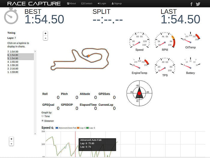
Swipe to the digital dash page and you should see data for Coolant, Oil Temp, Throttle and brake!
Real-Time Telemetry
Just 4 wires - Power, Ground, CAN+ and CAN- is needed to stream tons of data to race-capture.com for monitoring engine, driver and suspension performance!
Troubleshooting
If you don't see any data, verify all connections and splices.
If everything is connected connect your laptop to RaceCapture/Pro, open the RaceCapture/App, go to the Scripting section, set Logging Level to debug and select 'Poll logfile'. Check the output for any obvious errors.
If you are still having issues post your problem on the forums here http://www.autosportlabs.org/viewforum.php?f=20
CAN Channel Mapping
The full CAN bus mapping can be found in our CAN Database
Additional resources
- http://aimsportsystems.com.au/download/ecu/stock/bmw/BMW_Mini_100_eng.pdf - AIM docs for e46 M3 CAN codes
- http://www.diyelectriccar.com/forums/showthread.php/my-can-bus-gauge-solution-bmw-84882.html
- http://www.beisansystems.com/misc/SEIMENS_MS_420_ENGINE_CONTROL_SYSTEM.pdf
- http://www.bmwtech.ru/pdf/e46/ST034/2%20Driver%20Information%20Internet-1.pdf
- http://www.gadgetgangster.com/news/54-new-projects/556-the-car-kracker.html
- http://www.reslers.de/IBUS/index.html
- http://www.bimmerforums.com/forum/showthread.php?1887229-E46-Can-bus-project
- http://forum.e46fanatics.com/showpost.php?p=15754605&postcount=5

