MJLJ V4 kit assembly guide
Precautions
Surface mount Components
The soldering portion of this kit was NOT designed for beginners!

The Megajolt Lite Jr. makes extensive use of surface mount components.
Hand-soldering SMT components requires advanced soldering skills and a steady hand.
Individual parts are tiny, and are therefore easy to overheat and damage.
If you are not comfortable assembling this kit after reviewing the instructions, we recommend you purchase a ready-made and tested unit from our online store, offered at a reasonable price.
Before you Begin
Familiarize
Read the instructions completely before soldering your first component.
Do not lose parts
- Leave the parts in their bags and protective tape: Remove them just before soldering.
- Tiny flying parts: Be careful when extracting the parts from the tape- they can go flying if the protective tape is removed too quickly. Also, ensure you have a good grip on the part with your tweezers- a missed tweezer grab can send the part flying.
- Work surfaces and floor: Work in a clean and open area, preferably with hard floors: if a part falls off the bench or flies away from a missed tweezer grab, it will be easier to find.
Lighting
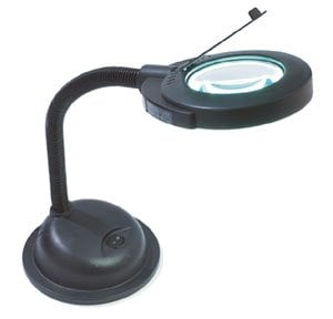
Use lots of good lighting- best is to use bright overhead lights combined with an illuminated magnifying glass.
Note part orientation
Some components, such as diodes and capacitors are marked with a band indicating their orientation. The markings on these components can be faint- especially with the diodes. Be sure to positively identify the component orientation before soldering- good lighting will help this tremendously.
Do not overheat
Small parts are easy to damage- use minimal heat required for soldering components. It is essential a recommended low wattage, fine-tipped soldering iron be used for assembly.
Assembling the kit
Tools you will need
Below are the essential tools you'll need for this project:
- A fine-tipped, low wattage soldering iron is necessary for precision work.
- Probably the best tool - a cross-action set of tweezers. This tool is normally closed, allowing you to hold parts with a relaxed grip and reduced tremors.
- Solder wick. Too much solder and you'll create ugly blobs and solder spikes. use this to clean up your joints by drawing away excess solder.
- A magnifying glass, preferably illuminated, is useful for identifying package markings and inspecting solder joints.
Parts Inventory
| Part | Type | Value | Photo |
|---|---|---|---|
| R1,R7 | Resistor | 100 ohms | |
| R2,R8 | Resistor | 1K | |
| R5,R6 | Resistor | 2.2K | |
| R9 | Resistor | 680 ohm | |
| D6,D7 | Schottky Diode | ||
| C3,C4,C5,C6,C7,C10 | Capacitor | 0.1uF | |
| C15 | Capacitor | 0.001uF | |
| C16 | Capacitor | 0.22uF | |
| C1 | Capacitor | 33uF 20v electrolytic | |
| C2 | Capacitor | 33uF 35v tantalum | |
| D1,D2,D3 | Diode | 1A 400v rectifier | |
| D4 | Diode | 12V Zener | |
| LED1 | LED | Right angle LED, green | |
| U1 | Integrated Circuit | MJLJ V4 Processor Freescale MC908QB8 | File:MC908QB8.jpg |
| IC1 | Integrated Circuit | ULN2003 Transistor Array | File:ULN2003.jpg |
| U2 | Integrated Circuit | MAX232A Transceiver (or equivalent) | File:MAX232a.jpg |
| U3 | Integrated Circuit | LM2937-5.0 voltage Regulator | |
| QG1 | Oscillator | 16MHz oscillator | |
| IC1,U1 | Sockets | 16 Pin DIP Socket | File:PDIP-16 socket.jpg |
| X1 | Connector | RJ-11 jack | File:RJ11 jack.jpg |
| X2 | Connector | Molex Right angle, 16 position | File:Molex minifit right angle pcb.jpg |
| Part | Type | Value | Photo |
|---|---|---|---|
| R3 | Resistor | 1K | |
| C11 | Capacitor | 0.1uF | |
| C12 | Capacitor | 0.001uF | |
| C13 | Capacitor | 0.22uF | |
| C14 | Capacitor | 15uf | |
| D5 | Diode | Schottky Diode | |
| L1 | Inductor | 1uH |
| Part | Type | Value | Photo |
|---|---|---|---|
| R4 | Resistor | 270 ohm | |
| C8,C9 | Capacitor | 0.1uF | |
| PS1 | Sensor | MPX4250ap | File:MPX4250ap.jpg |


