MJLJ V3 kit assembly guide
Assemble Power Supply
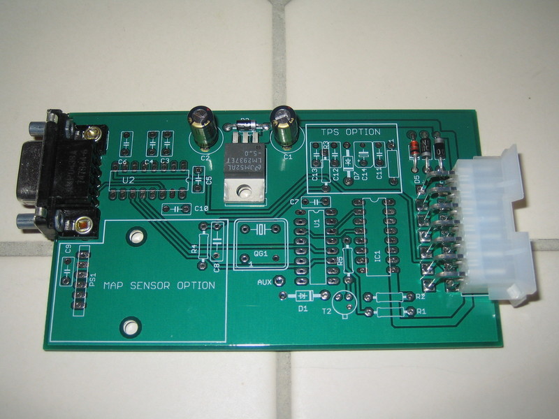
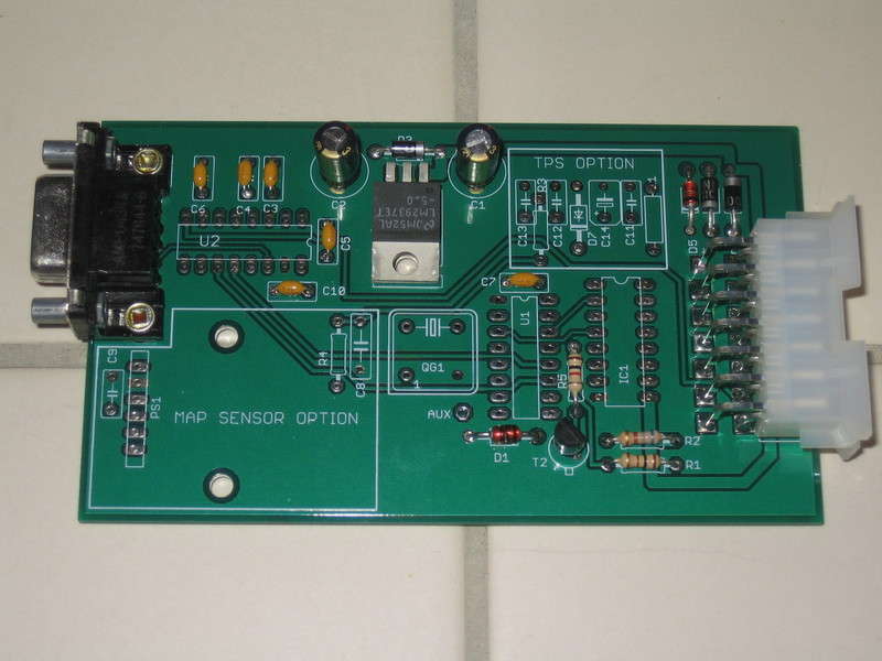
Begin by mounting and soldering the following components:
| Part Number | Description |
|---|---|
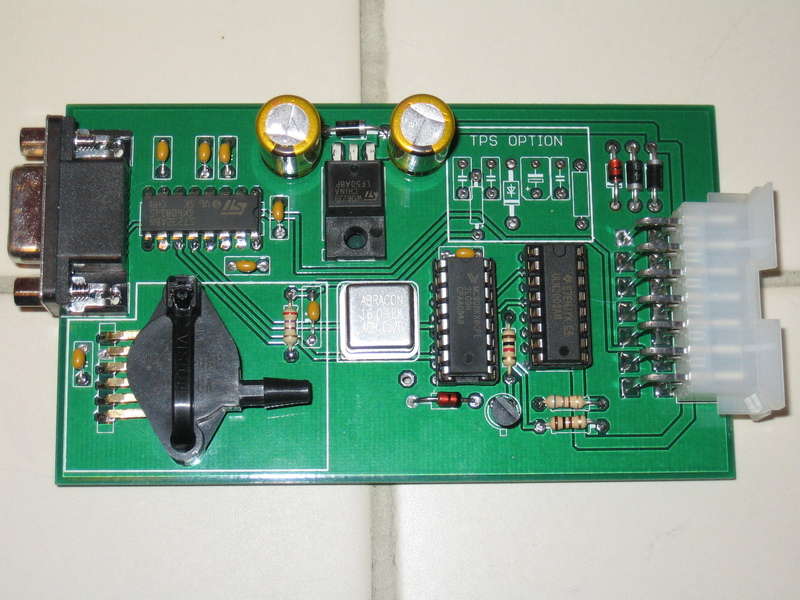
| X1 | Right angle DB9 connector. Snap the connector in so it is flat against the board. |
| X2 | Molex Mini-Fit 14 position right angle receptacle. Mount the connector so it rests perfectly flat against the board. This is important for proper fitment into the case. |
| C1,C2 | 33uf Electrolytic capacitors |
| U3 | Voltage Regulator- LM2937ET-50 5V or STMicro LF50 5V . Bend the legs at right angle so the metal back of the device is flat against the board. |
| D2,D3,D4 | 1N4004 1A 400V Diode. Note band orientation! |
| D5 | 1N4742 12V Zener Diode. Note band orientation! |
Verify power supply operation
Now that you have built the power supply, you should verify it's proper operation before you move on to the next assembly step.
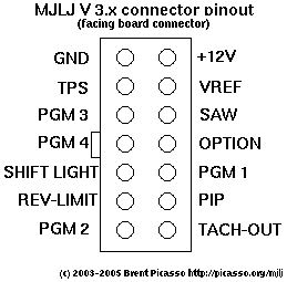
If you haven't already built your MJLJ wiring harness using the 14 pin Molex plug, now would be a good time. To perform this test you will need to provide at least GND and +12v to the MJLJ.
If you need to, refer to the MJLJ connector diagram:
Power up the MJLJ using a power supply that supplies at least 6v. A 9v battery works great for this.
You will need to verify that your board has the proper voltages in the right locations. Check the following:
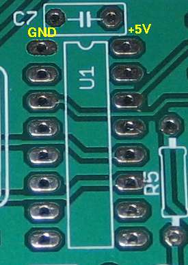
Device U1 - the Motorola MCHC08KX8 microcontroller. Verify +5v on the pads shown below.
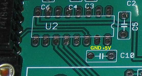
Device U2 - the MAX232 RS232 Transceiver. Verify +5v on the pads shown below.
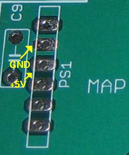
Device PS1 - the MPX4250 Pressure sensor. Verify +5v on the pads shown below.
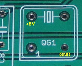
Device QG1 - the 16MHz Oscillator. Verify +5v on the pads shown below.
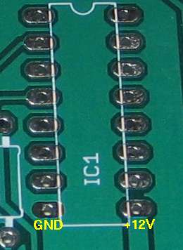
Device IC1 - the ULN2003 transistor array. Verify +12v (or whatever your supply voltage is).
If all check pass, great! Move on to the next step. If you are not reading proper voltages at the locations specified above, DO NOT proceed to the next step until you resolve the issue.
If you have problems, double check solder joints on all of the connections. You will have likely missed a joint or you might have one that does not have a solid connection. Refer back to the information on how to make a good solder joint if you need a refresher.
Install discrete components
Now you can install the discrete components!
Mount and solder the following parts:
R5||1K ohm 1/4W 5% tolerance resistor. Markings: brown-black-red-gold| Part number | Description |
|---|---|
| C3,C4,C5,C6,C7,C10 | 0.1uF ceramic capacitor. Bend the leads close to the body of the capacitor. |
| D1 | 1N4733 5V Zener Diode. Be careful installing this device since you will likely have the glass version, and it's a bit fragile. Bend the leads accurately so the device slides into the board and mounts flush to the surface. Note band orientation! |
| T2 | 2N2222 NPN switching transistor. Install with the flat side facing the upper right hand corner, with the molex connector to your right. (See picture) There is no T1, by the way. :) |
| R1 | 100 ohm 1/4W 5% tolerance resistor. Markings: brown-black-brown-gold |
| R2 | 680 ohm 1/4W 5% tolerance resistor. Markings: blue-silver-brown-gold |
Re-verify power supply operation
After adding the last set of parts, it's strongly recommended that you re-verify proper power supply voltages. Power up the board the same way you did previously and check the following with a volt meter:
Device U1 - the Motorola MCHC08KX8 microcontroller. Verify +5v on the pads shown below.
Device U2 - the MAX232 RS232 Transceiver. Verify +5v on the pads shown below.
Device PS1 - the MPX4250 Pressure sensor. Verify +5v on the pads shown below.
Device QG1 - the 16MHz Oscillator. Verify +5v on the pads shown below.
Device IC1 - the ULN2003 transistor array. Verify +12v (or whatever your supply voltage is).
If all check pass, great! Move on to the next step. If you are not reading proper voltages at the locations specified above, DO NOT proceed to the next step until you resolve the issue.
Again, if you have problems, double check solder joints on all of the connections, verifying you used the proper soldering technique.
Install active components
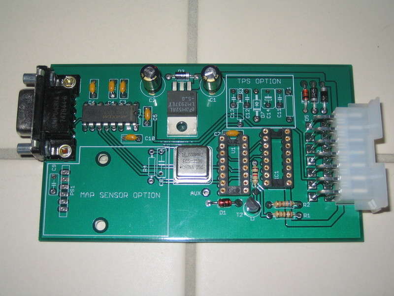
Next install the active components and IC sockets.
| Part Number | Description |
|---|---|
| QG1 | 16MHz oscillator. Make sure the sharp corner on the device matches the sharp corner on the board's silkscreen |
| U2 | Maxim MAX232 RS232A transceiver (or equivalent). Be sure to match the notch of the chip with the notch depicted by the silkscreen! |
| IC sockets | Install both 16 pin IC sockets. Be sure to match the notch of the socket with the notch depicted by the silkscreen! |
Optioning the board for MAP or TPS
MJLJ V3 offers the ability to configure engine load sensing with either a Manifold pressure sensor (MAP) or a Throttle Position Sensor (TPS).
It is up to your application to determine which is best for you; if you have multiple carburetor/throttle bodies and a very lumpy cam, it may be difficult to get a good MAP sensor reading, so TPS might be your route.
If you can get a good MAP sensor reading, this would be your best option, since it more directly measures engine load, and compensates for changes in Volumetric Efficiency (how well the engine breathes), such as engine modifications or different altitudes.
IMPORTANT! DO NOT configure the MJLJ with both MAP AND TPS!! You must choose one or the other
MAP Sensor Option
(Skip below if installing TPS)
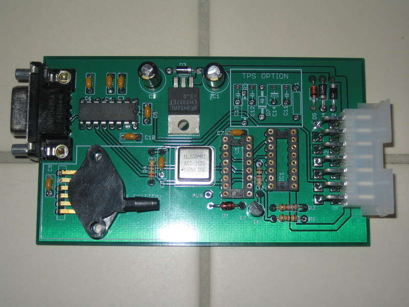
Mount and solder the following components:
| Part Number | Description |
|---|---|
| C8,C9 | 0.1uF ceramic capacitor |
| R4 | 270 ohm 1/4W 5% tolerance resistor. Markings: red-violet-brown-gold |
| PS1 | Motorola MPX4250AP 2.5 Bar pressure sensor. Bend the leads at a 90 degree angle, so when it is mounted, the vent on the case points down, and the part identification points up (see picture). Also, the pin with the notch should face the DB9 serial connector. The pins should be bent right where they become wider, before they go into the case of the pressure sensor. |
TPS sensor option
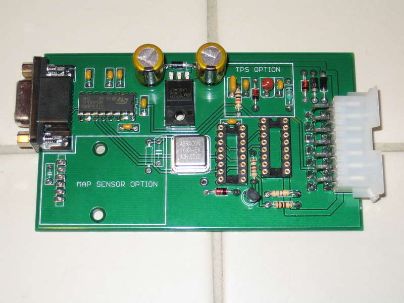
To install support for TPS, mount and solder the following components:
| Part Number | Description |
|---|---|
| R3 | 1K ohm 1/4W 5% tolerance resistor. Markings: brown-black-red-gold |
| C11 | 0.1uF ceramic capacitor |
| C12 | 0.001uF ceramic capacitor |
| C13 | 0.22uF ceramic capacitor |
| C14 | 4.7uF Tantalum Capacitor. This capacitor is polarized! Match the "+" marking on the body of the capacitor with the "+" on the circuit board's silkscreen. |
| D7 | 1N4733 5V Zener Diode. Be careful installing this device since you will likely have the glass version, and it's a bit fragile. Bend the leads accurately so the device slides into the board and mounts flush to the surface. Note band orientation! |
| L1 | 1uH Ferrite core inductor |
Final board assembly
To complete the assembly, install the programmed MC68HC908XK8 microcontroller and ULN2003 IC into their respective sockets.
The microcontroller plugs into the socket near the middle of the board; be sure the notch on the IC matches the socket- it should point up when viewing the board with the Molex connector facing the right.
The ULN2003 Transistor array plugs into the socket between the microcontroller and the molex connector. As with the microcontroller, ensure the notch on the device matches the socket. It should point in the same direction as the microcontroller.
It would be a good idea to do a final power-up test, checking voltages and ensuring nothing 'smokes' :)
It's also recommended that you secure the MAP sensor to the board- A small nylon "zip tie" is a quick and convenient way of doing this. For high vibration environments, you may also want to fasten the voltage regulator (U3) to the board with a small screw and nut.
You are now complete with the board assembly!
Case installation
MAP Sensor
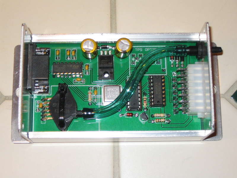
Install the plastic bulkhead fitting in the end plate which has the large, notched square hole. Install the fitting so the plastic nut faces the inside of the case. Be sure not to over torque the plastic nut.
If needed, wet the end of the short section of hose with a small amount of water and press it onto the MAP sensor. Repeat the same by pushing the hose onto the bulkhead fitting.
You can now slide the board into the case. If provisioned with a MAP sensor, the board slides into the case from one direction only, due to interference with the edge of the sensor and the case.
TPS Sensor
Slide the board into the case so the respective end plates align with the board connectors. You can install the two plates on either side of the case with two screws each, which allows you a final inspection before installing the top portion of the case.
When you are satisfied with your work, install the top of the case with the remaining screws.
Vehicle installation
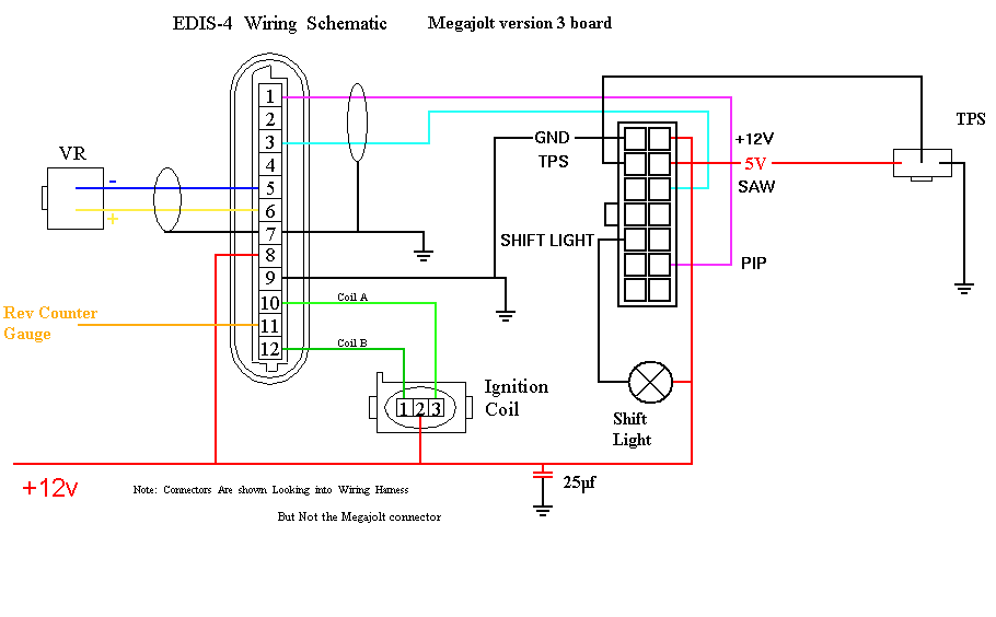
This is a representative wiring diagram for an EDIS-4 application. EDIS-6 or EDIS-8 will have their corresponding connectors (TODO add EDIS-6 and 8 wiring diagrams)
Wiring notes and guidelines
- Use shielded cable for the VR Sensor, and the PIP/SAW signal between the MJLJ and EDIS module. Be sure to ground the shield as well. Also note the VR sensor is polarized- you will not get spark from the EDIS module if it is wired backwards.
- Minimize supply voltage variances and ground loop problems: It's strongly recommended you power the EDIS module and MJLJ from the same electrical circuit. Also, ground both at the same point on the chassis.
- The MJLJ should be installed inside the passenger compartment. It's not designed to handle the temperature extremes of the engine bay, and unless you installed it in a weather tight case or potted the whole thing in expoxy, you should keep it away from moisture.
- For MAP based setups ignore the TPS connections.
OEM tach adapter
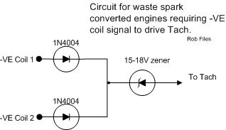
Many tachometers can accept the 12V signal emitted from the MJLJ module. however, some OEM tachs detect the RPM signal by sensing the high voltage flyback pulse from the ignition coil. In distributor based setups, there is only one ignition coil to detect this pulse from. With a wasted spark system like the Ford EDIS, you will have multiple coils providing this signal. Consequently you may need a way to detect this pulse across multiple coil-packs.
The following circuit allows the flyback pulse to be detected across individual coil packs while still isolating the coils from each other:
