RaceCapturePro installation guide
Overview
Installation
Mounting orientation and position
The ideal mounting position for RaceCapture/Pro is mounted flat (right side up or upside down), in the exact center of the vehicle. This gives the best effect from the built in Gyroscope, which measures Yaw (understeer / oversteer).
<<Todo: add picture or diagram here>>
Shock isolation mounting
In very harsh environments you may want to mount RaceCapture/Pro using rubber isolators. Source of vibration isolating mounts
Default Accelerometer Configuration
The default accelerometer configuration assumes RaceCapture/Pro is mounted flat, right side up with the terminal block pointed towards the front of the vehicle. Other orientations are supported by changing the settings in the Software. See the Operation Guide for more information.
<<Todo: add picture or diagram here>>
RaceCapture/Pro External Connections
Terminal block connections
Connections facing terminal block, from left to right. 20 gauge wire works well for the connections.
- Ground
- +12v
- Analog/Frequency out 4
- Analog/Frequency out 3
- Analog/Frequency out 2
- Analog/Frequency out 1
- +5V Voltage reference
- Analog input 7
- Analog input 6
- Analog input 5
- Analog input 4
- Analog input 3
- Analog input 2
- Analog input 1
- General purpose input/output 3
- General purpose input/output 2
- General purpose input/output 1
- Frequency/pulse input 3
- Frequency/pulse input 2
- Frequency/pulse input 1
Power Connection
Connect RaceCapture/Pro to a power source between 9 and 24V. To fully support all devices and outputs, provide at least a 5A fused connection.
Analog Inputs 1-7
- Active Sensors/Signals
The Analog Input Channels accept a 0-5v input signal (protected up to 45V). Connect the input from a sensor to the appropriate connection of the terminal block.
- Resistive sensor
When connecting resistive style sensors, like many temperature and pressure sensors, one terminal of the sensor is connected to ground, and the other is connected to the Analog input, with a pullup resistor connected to the +5V Voltage Reference on the terminal block. A 2.2K resistor is recommended for most applications.
5V Voltage Reference
This output provides a 5V reference to be used with the Analog Inputs. Up to 50mA is provided to supply power to active sensors, pull-up resistors and other purposes. This reference output is protected against short-circuits with an auto-resetting fuse. If the fuse is active, a low or zero voltage reading may be observed on this port. To verify an over-current situation, test the voltage on the port without any load connected.
Analog/Frequency Outputs 1-4
Depending on configuration, these outputs provide a settable 0-5v analog output voltage, or frequency output where the pulse-width and frequency can be set. These outputs can supply 50mA each.
General Input/Output Channels 1-3
Depending on configuration, these channels can accept either a digital input, or provide an output to control external devices.
- When configured for input, the channel accepts a 0-5v input (protected up to 45V). Each input channel has a built-in 10K pullup resistor connected to 5V.
- When configured for output, the channel provides an open-drain output that can drive 1A and is thermal / over-current protected with inductive load clamping. When the output is deactivated, a 1K ohm pull-up to +5v is present.
Frequency/Pulse Input 1-3
These input channels can be used to time the duration between digital pulses for purposes of measuring RPM, shaft speed, and so on. The input accepts 0-5V (protected up to 40V). Each input has a built-in 10K pullup resistor connected to 5V.
TACH SIGNAL NOTES
Do not connect the old-style tachometer signal directly to RaceCapture/Pro. This signal is typically sourced from a wire that connects directly to the (-) post of the ignition coil. These signals are 400-500v peak and can damage your RaceCapture/Pro hardware.
Interfacing directly to the signal of the coil pack primary will require an opto-isolated interface board such as the design here, currently under testing. Other interface boards can be used, provided they provide a clean square wave signal to RaceCapture/Pro.
Newer style tach signals sourced from the ECU will likely provide a clean square wave signal and can be connected directly to this input.
If unsure, observe the signal with an oscilloscope and/or consult technical documentation of your vehicle.
Expansion Port
The RJ45 Expansion port located next to the terminal block is provided for future sensor / control expansion.
SD Card Slot
The SD card slot is used to store datalogging sessions. 512MB to 32GB cards are supported.
USB Port
Used for configuring RaceCapture Pro via Race Analyzer.
LED Indicators
- Power LED
Indicates the unit is powered up (via 12v supply or USB)
- LED1
Indicates GPS Activity. Slow flash (1Hz) indicates GPS is actively acquiring. Fast flash (10 times per second) indicates GPS is locked on to satellites.
- LED2
Indicates SD card Logging Activity. The flash rate matches the channel with the highest configured logging rate.
- LED3
Indicates error status when writing to SD Card (future error conditions will be indicated by this LED)
Pushbutton
Press to manually start / stop a logging session. Note this may be overridden by any on-board scripts that may automatically start or stop logging.
Communication Ports
The communication ports a standard RS232 serial connection with power (up to 5v at 1.5A)
- Port 1
Used for telemetry expansion module
- Port 2
Used for GPS module
Internal Switches / Jumpers
4 position DIP switch (SW1)
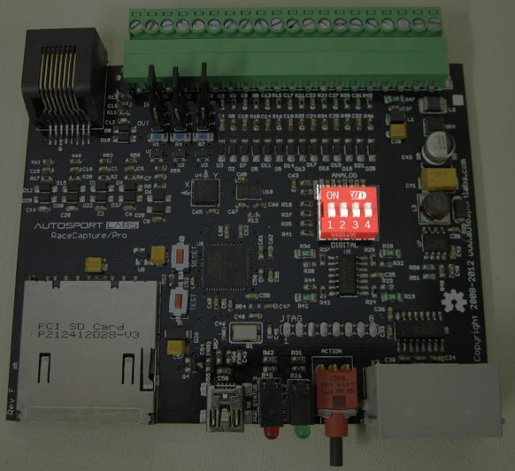
This switch bank configures the 4 outputs for Analog or Frequency/PWM mode. To enable analog mode for a particular output channel, slide the switch for the selected channel to the 'on' position. For Frequency/PWM mode slide the switch to 'off'.
GPIO configuration jumpers
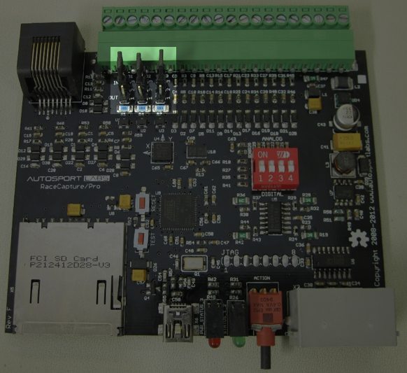
The array of jumper blocks configures the 3 GPIO channels for either digital input or output. To configure a particular channel, move the jumper to either the IN position (for input) or OUT (for output)
Reset Pushbutton
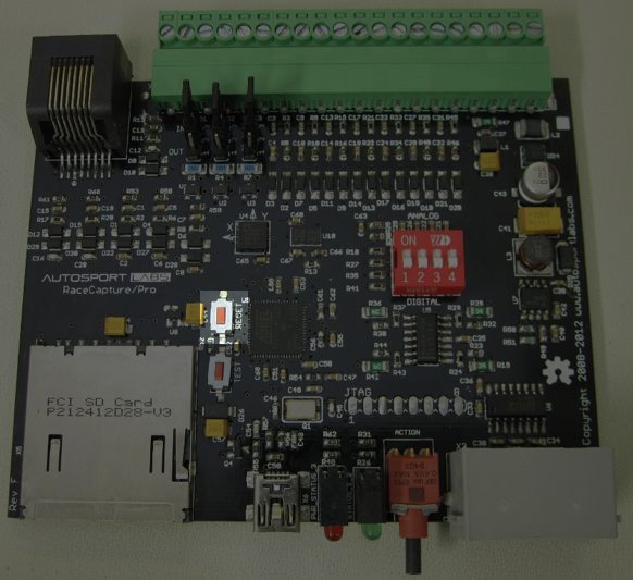
The reset push-button, if installed, is used as a hard reset for the running firmware.
Test Pushbutton
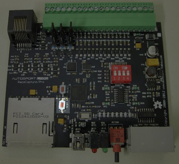
The test push-button, if installed, is used to load the factory bootloader for re-writing flash. Also see: How to flash RaceCapture/Pro firmware
JTAG header
The JTAG header is used to debug or program the RaceCapture/Pro firmware. This is not needed for normal operation


