RacecapturePro MK3 hardware install
Installation
Orientation
Connections
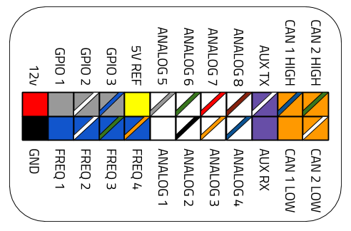
Main Connector Pinout
GPS
Connect the included GPS antenna to this port.
- Note Tighten this connection to 5-6 inch/lbs (just beyond finger tight). Do not over torque
Cellular Telemetry
If optioned with the 3.5G real-time cellular telemetry module, connect the cellular antenna to this port.
- Note Tighten this connection to 5-6 inch/lbs (just beyond finger tight). Do not over torque
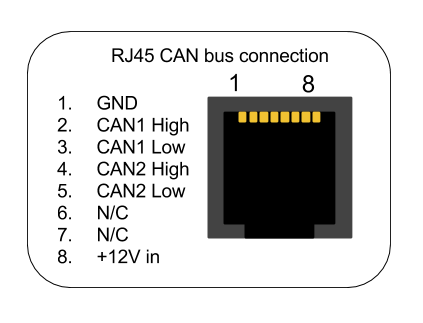
RJ45 CAN + Power connection
The RJ45 port provides connections for power and both CAN channels.
OBDII CAN cable
The RJ45 port is normally provided for the OBDII CAN cable accessory for a convenient plug and play OBDII connection
Custom Cable
You can also use a common RJ45 ethernet cable to provide power, ground and CAN bus data for a custom application.
| Connection | CAT5 EIA-T568B RJ45 cable |
|---|---|
| +12v | Brown |
| Ground | Orange/White |
| CAN 1 High | Orange |
| CAN 1 Low | Green/White |
| CAN 2 High | Blue |
| CAN 2 Low | Blue/White |
Note: These color codes assume EIA-T568B RJ45 cable (check printing on the cable to confirm)


