AIM Integration CAN Mapping
AIM Data to Race Capture Pro Integration
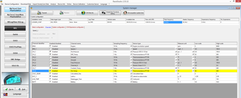
1) Configure your AIM channels/sensors in AIM Race Studio → Channels
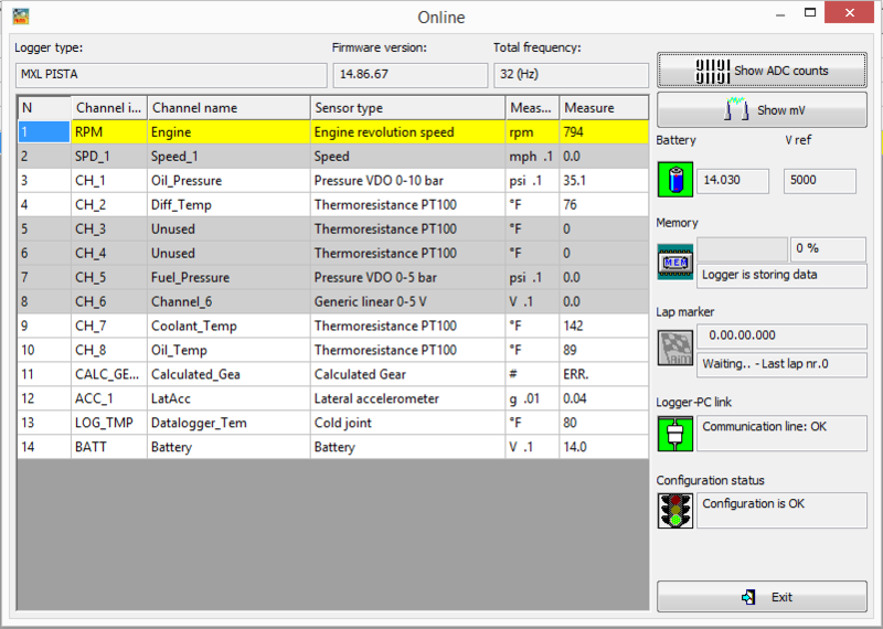
2) Use AIM Online tool to verify channels
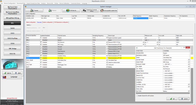
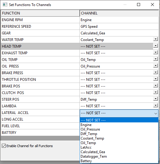
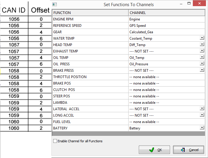
3) Click AIM SmartyCam Functions settings to setup the channels you want exported to RCP
Map your AIM Sensors/Channels to AIM SmartyCam Functions. Each AIM SmartyCam Function data is then sent over on the CAN Bus via a specific CAN Channel ID, and CAN Offset (more on this later).
Screen Capture or save your Functions to Channels mappings as you will need them later when you look for the CAN Channel ID and Offset for the AIM Function you mapped you sensor channel to.
Here is an example.
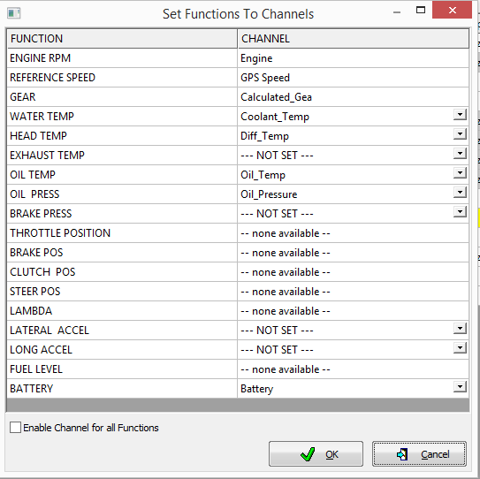
If you need more channels than the ones that AIM allows you to select, you can check the ‘Enable Channel for all Functions’ box at bottom. Note, just because the AIM Function says something like CLUTCH POS, does not mean that you must use a Position Sensor for that Function. You could map a Temp Sensor, Fuel Sensor, or any sensor you have available. It is preferred to try to map a sensor that is similar to the default if possible though.
You will need to know which sensor you mapped to which AIM Functions in order to add those CAN Channels into RCP. Each AIM Function has a specific CAN Channel ID and Offset that does not change no matter what sensor is mapped to that Function (See Appendix A Table 2 at bottom of this document). Later we will be referring back to your AIM Functions to Channels mapping that you did here, so keep this window available.
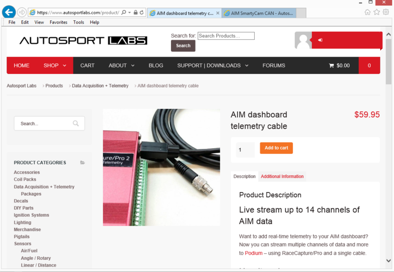
4) Connect AIM to RCP cable
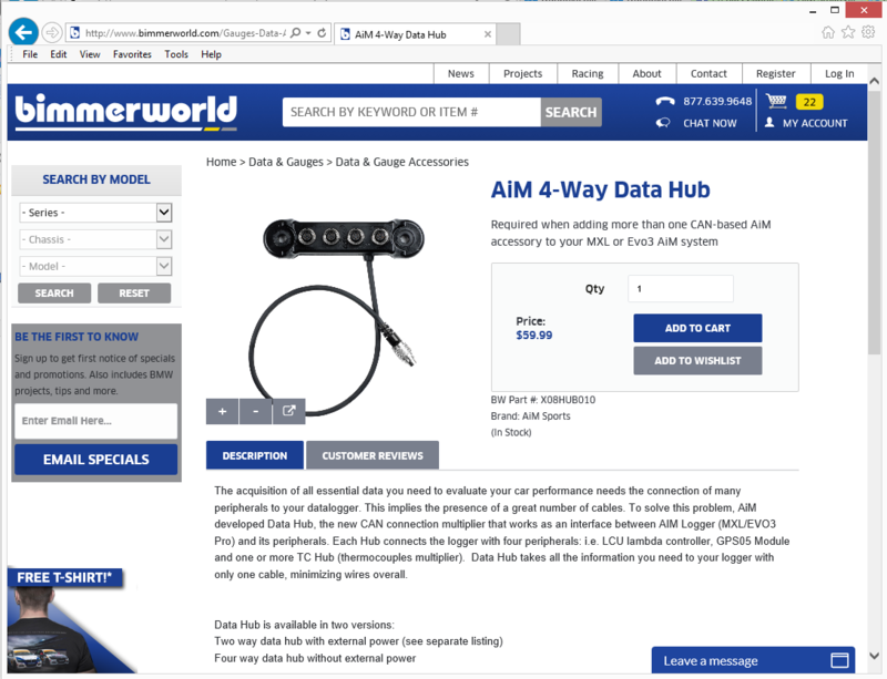
This cable has a 5 pin AIM plug on one end and an RJ45 plug for the CAN Bus jack of the RCP. You will probably need an AIM 4 port Data Hub in order to use AIM GPS and AIM-RCP cable, as AIM dash's only have one 5 pin port. Unplug GPS from back of dash, plug the hub into back of Dash, then plug GPS and AIM-RCP cable into hub.
https://wiki.autosportlabs.com/AIM_SmartyCam_CAN#Integration_Cable
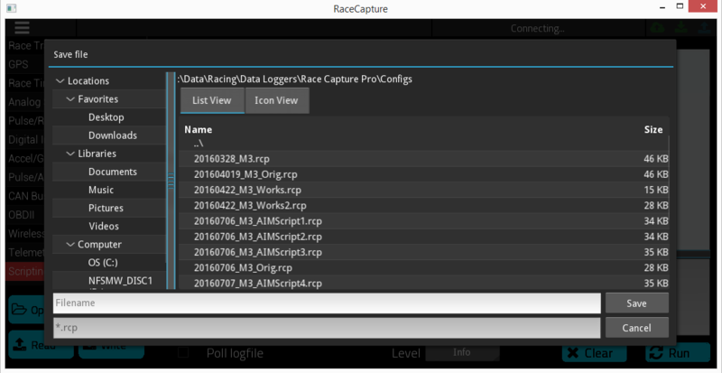
5) Open Race Capture App and save current Race Capture Settings to disk
Please note newer devices (Podium Connect) have wizards that will help you map your AIM channels so you may not have to do steps 6-12.
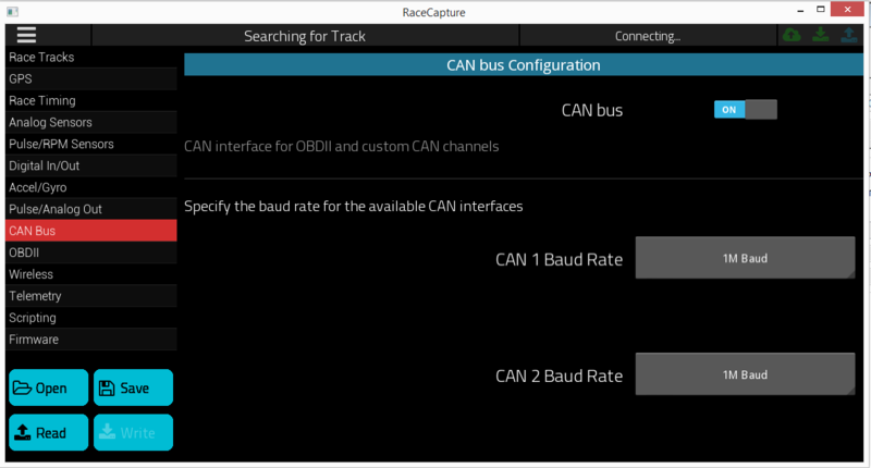
6) Turn on CAN Bus in Race Capture App and set the Baud rate to 1M
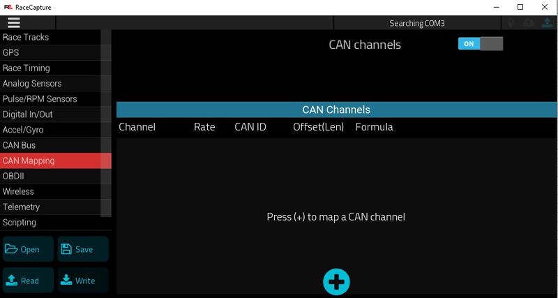
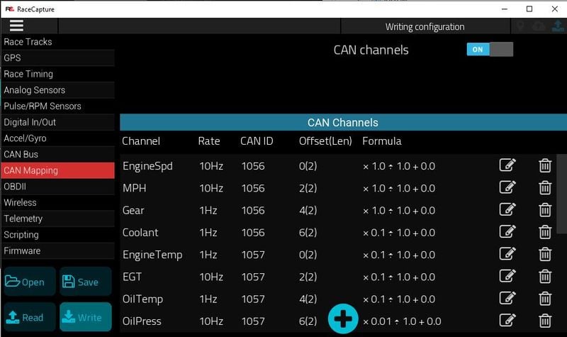
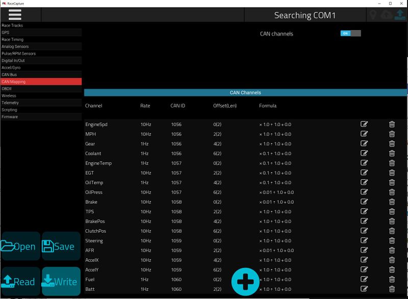
7) Turn on CAN Channel Mapping and add your AIM CAN Channels (click for video)
8) Click + Button to add a New Channel
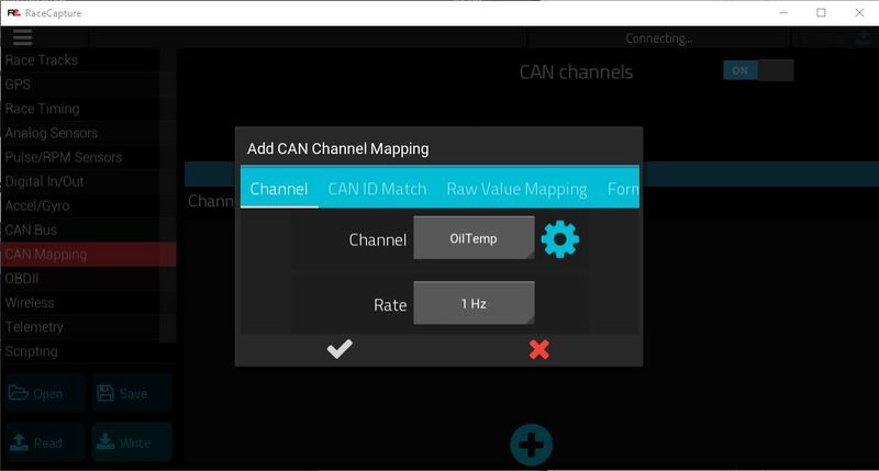
Select appropriate Channel Name from drop down. The RCP Channel name does not have to exactly match the AIM Channel name. Select Rate you want to log this piece of data at.
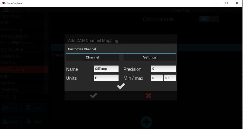
Customize Channel Info by clicking gear icon. This just changes how it is displayed in RCP.
Note: You cannot have 2 channels with same name in RCP. Ie. if you already have RPM in RCP, if you also add RPM via AIM, you need to name one of the channels to something different like EngineSpd.
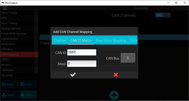
See Appendix A Table 2 below and find the AIM Function you mapped your sensor to in the AIM SmartyCam settings from step 3 above. Find the CAN Channel ID (1056, 1057, 1058, 1059, or 1060) and Offset (0, 2, 4, or 6) for that AIM Function and enter it here. Only look at AIM Function, CAN Channel, and CAN Offset for now. For example, as shown in Step 3, I mapped my DiffTemp sensor to the HEAD TEMP AIM SmartyCam Function, so looking at Table 2 my DiffTemp Sensor data would be on CAN Channel 1057 Offset 0.
Mask will be always be 0 and CAN Bus should be 1.
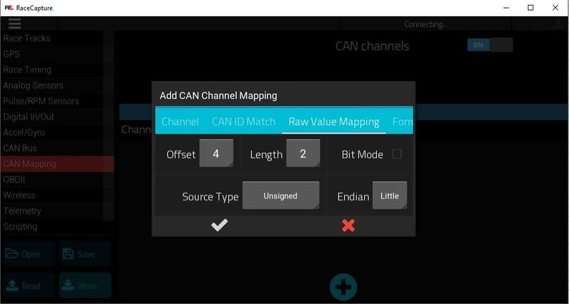
Select the correct Offset as shown below. Get correct Offset value from Table 2 as described above.
Length should be always be 2, and Endian should be set to Little for AIM.
Bit mode should be unchecked, and Source Type is Unsigned (defaults).
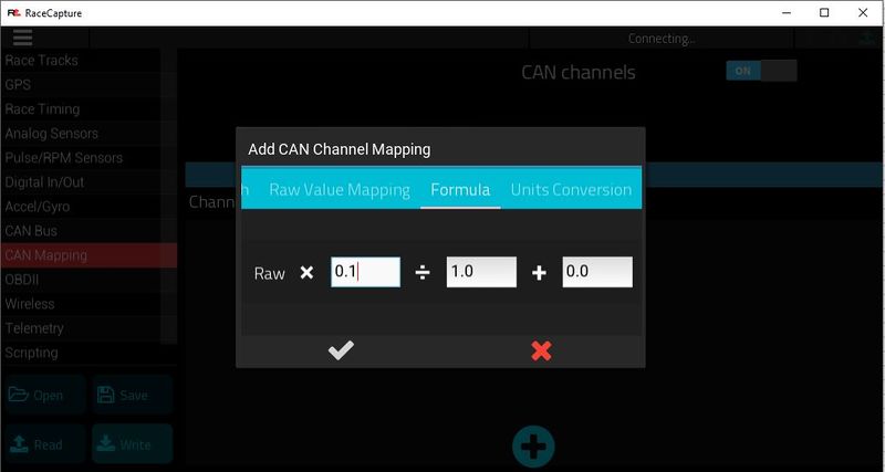
For most sensors the Multiplier will be 1, Divider will be 1, and Adder will be 0.
Most Temp Sensors will have a Multiplier of 0.1 (as shown in pic below).
Most Pressure sensors have a Multiplier of 0.01
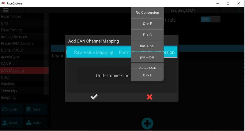
Most data coming over from AIM will be in metric units. Use the Units Conversion tab to convert the data to imperial units if needed.
Then hit the check mark icon to finish adding the channel.
9) Write your Config to RCP
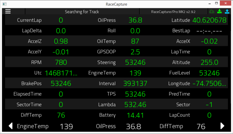
10) Check the RCP Dashboard to see if the AIM data has been imported correctly
11) Compare RCP Dashboard values against AIM Online tab
12) Rinse and Repeat steps 8-11 until you get it all of your AIM sensors/channels added correctly.
If you can’t get a specific channel to work, move on to a different one and see if you can get that working. Post any questions you have on the RaceCapture Support Facebook page or ASL Race Capture Forums.
Appendix A: AIM Function to CAN Channel Mappings
Table 1: AIM Functions mapped to your AIM sensor Channels
(from Step 3)
Use your mappings that you did in from Step 3 above. The pic below is just for reference. Substitute the channels that you used. ie. Whatever sensor you mapped to BRAKE PRESS, it will have a CAN ID of 1058 and OFFSET of 0.
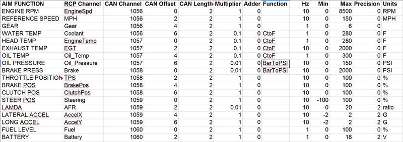
Table 2: AIM Function to CAN Channel and CAN Offset
(AIM Function correlates to table above)
Note: The RCP Channels shown below are the default examples, you would replace these with the sensors you actually used when mapping the AIM Functions to Channels from from Step 3 above. The CAN Channel, Offset, and Length is specific to the AIM Funtion. Ie. no matter what sensor you have mapped to EXHAUST TEMP, it will always have a CAN Channel ID of 1057, CAN Offset of 2, and CAN Length of 2. The suggested Multiplier, Adder, Function, Min/Max, Precision, and Units are specific to the Sensor, not the AIM Function. If you used a different type of sensor for an AIM Function, use the correct Multiplier, Min/Max, etc for that Sensor. The Hz, Min/Max, Precision, Units, etc are just suggestions for the types of sensors shown. Change to suit your needs. Ie if your car only revs to 6000, change max RPM from 8500 to 6500.
Table 3: Default example of RCP CAN Channel Mappings
(Channel name below correlates to RCP Channel in table above)
You can download an RCP Config file with these default AIM CAN Channel Mappings as shown above here. The Channel mappings (Channel Name, Hz, Channel Min/Max values, Multiplier, and Unit Conversion) will need to be edited and updated for whatever sensors you actually mapped in your AIM SmartyCam settings in Race Studio. You should also delete Channel Mappings you aren't using. IMPORTANT: Definitely either rename AccelX and AccelY if you mapped sensors to them or delete them if unused.
Example: If in Step 3 above, you mapped your DiffTemp sensor/channel to the EXHAUST GAS Function in the AIM SmartyCam settings, you would edit the EGT Channel in RCP and change it to DiffTemp. Because EGT and DiffTemp are both Temp Sensors, the Multiplier and conversions probably would not need to be changed. Min/Max would need to be changed (EGT Max is like 2000 but DiffTemp Max is like 300). If instead you mapped a pressure sensor to EXHAUST GAS Function, you would need to change the Multiplier to 0.01 from the default of 0.1.
CAN Channel Mapping Notes:
1) Channel name is what will show up in your RCP and Podium display. It does not have to exactly match the name you used in AIM.
2) You cannot have 2 Channels in RCP with the same name. Therefore if you already have RPM or EngineTemp or whatever wired into your RCP, you should Customize your AIM CAN Channel name to be slightly different (ie EngineSpd instead of RPM, or Batt instead of Battery).
3) Customizing the Channel Values (click gear icon) allows you to pre-set the Min/Max values for RCP/Podium Analysis graphs.
4) Precision is how many decimal points you want recorded and displayed.
5) Units is just what you want displayed after the value. Ie. setting it to F does not automatically convert it to Fahrenheit for example. You must do all conversions in the Units Conversion tab.
6) Find the CAN ID and Offset for your current sensor by looking in Table 2 above and seeing which CAN Function you mapped your sensor to in the AIM SmartyCam settings from Step 3 at top of this document. Ie if you mapped your DiffTemp sensor to the HEAD TEMP Function in the AIM SmartyCam settings, it would have a CAN ID of 1057 and an Offset of 0.
7) Think of CAN ID and CAN Offset as rows and columns in a spreadsheet. CAN ID would be a row, and CAN Offset would be a Column. You obviously cannot have 2 Channels with the same CAN ID and CAN Offset. The AIM SmartyCam Function name is just the variable name used to store your data for the sensor you mapped to it.
8) MASK should be set to 0 for all AIM channels.
9) CAN Bus should be set to 1 for all AIM channels (unless you wired the AIM CAN wires directly to CAN 2 in back of RCP).
10) All of the AIM CAN data has a CAN Length of 2.
11) Bit Mode should be unchecked for all channels.
12) Source Type should be Unsigned for all AIM channels.
13) Endian should be set to Little for all AIM channels.
14) Most channels will have a Multiplier of 1.0, almost all should have a Divider of 1.0, and almost all should have an Adder of 0.0. See Table 2 above for common Multiplier values.
15) Most Temp Sensors have a Multiplier of 0.1 and will probably need to be converted from C→F.
16) Most Pressure Sensors have a Multiplier of 0.01 and will probably need to be converted from Bar→PSI.
17) Almost all data output in AIM is in metric so you may need to convert to imperial units if needed using the Units Conversion tab.
18) AIM has a CAN baud rate of 1M. It will not work if set to 500k or other value.

