Dual LED cluster
Images for the Dual LED cluster
Dual LED cluster
Assembly instructions
Before starting
- Do not switch the Red and blue LEDs! Due to voltage differences it is critical you use the red LEDs in the inner ring of the array and blue LEDs in the outer.
- If you feel you need to test the LEDs before installing- for example, if you mixed up the LEDs, you can test the individual LEDs by applying 2V to the red LEDs and 3V to the blue LEDs. Do not exceed the rated voltage or you will damage the LED!
Red cluster
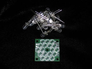
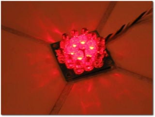
Insert the Red LEDs into the inner ring of the printed circuit board. Ensure the flat side of the LED matches the flat on the circuit board. Also check that the LED is flat against the circuit board- bend the leads on the back side of the board at an angle to keep the LEDs from falling out.
Blue cluster
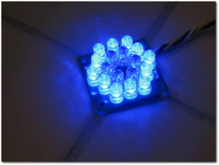
Repeat the same procedure for the Blue LEDs, inserting the LEDs into the outer ring of the circuit board.
Jumper wires for R1 and R2
Use a small jumper wire- or trimmed LED lead- to brige R1 and R2. Alternatively, you can also use these pads to wire in a resistor should you wish to reduce the array's brightness.
Wiring
- Connect +12V to +12 power, preferably switched ignition supply
- Connect A1 (RED array) and A2(Blue array) to ground via a switch, relay, or through one of the user defined outputs if you are controlling this cluster with the MegaJolt Lite Jr. See the wiring diagram for the MJLJ version you are running for more information.


