Harness specifications: Difference between revisions
No edit summary |
|||
| (19 intermediate revisions by the same user not shown) | |||
| Line 1: | Line 1: | ||
https://i.imgur.com/sZcvrLp.mp4 | |||
=Plug and Play harness system= | =Plug and Play harness system= | ||
[[#Analog_harness|Jump to the Analog/Digital Harness system]] | [[#Analog_harness|Jump to the Analog/Digital Harness system]] | ||
| Line 8: | Line 10: | ||
rect 162 3 551 737 [[#Dual_CAN_splitter|]] | rect 162 3 551 737 [[#Dual_CAN_splitter|]] | ||
rect 618 8 930 531 [[#Dual_CAN_interconnect|]] | rect 618 8 930 531 [[#Dual_CAN_interconnect|]] | ||
rect 577 538 969 784 [[# | rect 577 538 969 784 [[#Powered_dual_CAN_hub|]] | ||
rect 277 914 685 1491 [[#CAN_extension|]] | rect 277 914 685 1491 [[#CAN_extension|]] | ||
rect 217 1503 669 2345 [[#CAN_splitter|]] | rect 217 1503 669 2345 [[#CAN_splitter|]] | ||
rect 300 2452 723 2643 [[#Inline_CAN_terminator|]] | rect 300 2452 723 2643 [[#Inline_CAN_terminator|]] | ||
rect 60 2767 258 3543 [[#Power_CAN_pigtail|]] | rect 60 2767 258 3543 [[#Power_CAN_pigtail|]] | ||
rect 503 3510 948 3697 [[ | rect 503 3510 948 3697 [[AnalogX2|]] | ||
rect 479 3341 906 3512 [[ShiftX3|]] | rect 479 3341 906 3512 [[ShiftX3|]] | ||
rect 488 3127 907 3333 [[TireX|]] | rect 488 3127 907 3333 [[TireX|]] | ||
| Line 19: | Line 21: | ||
==Analog harness== | ==Analog harness== | ||
The plug and play Analog/Digital harness system lets you easily connect individual sensors to your RaceCapture system, without the need to splice, crimp, or heat shrink connections. Multiple-length extension cables for each | The plug and play Analog/Digital harness system lets you easily connect individual sensors to your RaceCapture system, without the need to splice, crimp, or heat shrink connections. Multiple-length extension cables for each level lets you build a harness that perfectly matches your installation needs. | ||
* '''Note:''' The same 8 channel connector (and downstream connectors) can plug into an M12-12P analog port or the M12-12P digital port of the system. | |||
Click on the items within the image to see details. | Click on the items within the image to see details. | ||
<imagemap>Image:combined_analog_harnesses.jpg|Subtitle of Image Map combined_analog_harnesses.jpg | <imagemap>Image:combined_analog_harnesses.jpg|Subtitle of Image Map combined_analog_harnesses.jpg | ||
rect | rect 309 18 630 707 [[#8_channel_extension|]] | ||
rect | rect 222 710 573 1408 [[#8_to_4_channel_splitter|]] | ||
rect | rect 581 709 882 1385 [[#8_channel_pigtail|]] | ||
rect | rect 405 1414 762 1942 [[#4_channel_extension|]] | ||
rect | rect 173 1962 532 2669 [[#4_channel_splitter|]] | ||
rect | rect 516 1962 773 2478 [[#4_channel_pigtail|]] | ||
rect | rect 299 2675 673 3143 [[#Single_channel_extension|]] | ||
rect | rect 166 3176 268 3789 [[#Single_channel_pigtail|]] | ||
rect | rect 310 3176 410 3840 [[#Pressure_sensor|]] | ||
rect | rect 441 3176 545 3725 [[#Linear_temperature_sensor|]] | ||
</imagemap> | </imagemap> | ||
| Line 38: | Line 43: | ||
==Dual CAN splitter== | ==Dual CAN splitter== | ||
M8-6P male to dual M8-4P female splits CAN1/CAN2 into individual CAN1 and CAN2 connections. [https://www.autosportlabs.com/product/can1-can2-dual-can-splitter/ Product Info] | M8-6P male to dual M8-4P female splits CAN1/CAN2 into individual CAN1 and CAN2 connections. [https://www.autosportlabs.com/product/can1-can2-dual-can-splitter/ Product Info] | ||
Limited power (1A @ 12v) is provided to devices connected to CAN1 and CAN2. For higher power requirements, please use the [[#Powered_dual_CAN_hub|Powered Dual CAN Hub]] | |||
* A connection: connects to CAN1 | |||
* B connection: connects to CAN2 | |||
[[image:ASL_DUAL_CAN_SPLITTER_diagram.jpg]] | [[image:ASL_DUAL_CAN_SPLITTER_diagram.jpg]] | ||
| Line 44: | Line 54: | ||
==Dual CAN interconnect== | ==Dual CAN interconnect== | ||
M8-6P male to M8-6P male link cable for connecting two CAN bus networks to our Powered Dual CAN Hub [https://www.autosportlabs.com/product/racecapture-m8-to-dual-can-bus-link-cable/ Product Info] | M8-6P male to M8-6P male link cable for connecting two CAN bus networks to our [[#Powered_dual_CAN_hub|Powered Dual CAN Hub]]. 1 meter length. [https://www.autosportlabs.com/product/racecapture-m8-to-dual-can-bus-link-cable/ Product Info] | ||
[[image:ASL_DUAL_CAN_M8_1M_diagram.jpg]] | [[image:ASL_DUAL_CAN_M8_1M_diagram.jpg]] | ||
| Line 51: | Line 61: | ||
==Powered dual CAN hub== | ==Powered dual CAN hub== | ||
Powered CAN hub featuring 8 ports (4 ports for CAN1 and 4 ports for CAN2). Use with the [[Dual_CAN_interconnect|Dual CAN interconnect]] cable to link to your RaceCapture or PodiumConnect system. [https://www.autosportlabs.com/product/powered-8-port-dual-can-bus-hub-kit/ Product Info | Powered CAN hub featuring 8 ports (4 ports for CAN1 and 4 ports for CAN2). Use with the [[#Dual_CAN_interconnect|Dual CAN interconnect]] cable to link to your RaceCapture or PodiumConnect system. [https://www.autosportlabs.com/product/powered-8-port-dual-can-bus-hub-kit/ Product Info] | ||
[[image:powered_8_port_dual_can_hub_3quarter.jpg|500px]] | [[image:powered_8_port_dual_can_hub_3quarter.jpg|500px]] | ||
==CAN extension== | |||
==CAN | |||
M8-4P male to M8-4P female cable extends a CAN bus network. Available in 0.5, 1, 2, 3, and 4 meter lengths. [https://www.autosportlabs.com/product/can-bus-extension-cable/ Product Info] | M8-4P male to M8-4P female cable extends a CAN bus network. Available in 0.5, 1, 2, 3, and 4 meter lengths. [https://www.autosportlabs.com/product/can-bus-extension-cable/ Product Info] | ||
| Line 78: | Line 87: | ||
==Inline CAN terminator== | ==Inline CAN terminator== | ||
M8-4P male to M8-4P female inline 120 ohm CAN terminator - place one near end of the CAN bus network to ensure signal integrity. [https://www.autosportlabs.com/product/inline-can-terminator/ Product Info] | M8-4P male to M8-4P female inline 120 ohm CAN terminator - place one near end of the CAN bus network to ensure signal integrity. [https://www.autosportlabs.com/product/inline-can-terminator/ Product Info] | ||
* '''Note''': Only one terminator should be used at the end of the network/cable-run. | |||
[[image:ASL_CAN_TERMINATOR_diagram.jpg]] | [[image:ASL_CAN_TERMINATOR_diagram.jpg]] | ||
| Line 247: | Line 258: | ||
==Pressure sensor== | ==Pressure sensor== | ||
M8-3P male to 3 pin Delphi GT150 pressure sensor connector. 2 meter length. [https://www.autosportlabs.com/product/10-bar-150-psi-pressure-sensor-with-plug-and-play-harness/ 10 bar/150 PSI Product Info] [https://www.autosportlabs.com/product/150-bar-2175-psi-pressure-sensor-with-plug-and-play-harness/ 150 bar/2175 PSI Product Info] | M8-3P male to 3 pin Delphi GT150 pressure sensor connector. 2 meter length. [https://www.autosportlabs.com/product/10-bar-150-psi-pressure-sensor-with-plug-and-play-harness/ 10 bar/150 PSI Product Info] [https://www.autosportlabs.com/product/150-bar-2175-psi-pressure-sensor-with-plug-and-play-harness/ 150 bar/2175 PSI Product Info] | ||
{| class="wikitable" | |||
|- | |||
! M8 Pin !! GT150 Pin !! Connection | |||
|- | |||
| 1 || A || Ground | |||
|- | |||
| 3 || B || 5v Power | |||
|- | |||
| 4 || C || Signal | |||
|} | |||
[[image:ASL_DELPHI3_M8_diagram.jpg]] | [[image:ASL_DELPHI3_M8_diagram.jpg]] | ||
Revision as of 04:12, 30 September 2022
https://i.imgur.com/sZcvrLp.mp4
Plug and Play harness system
Jump to the Analog/Digital Harness system
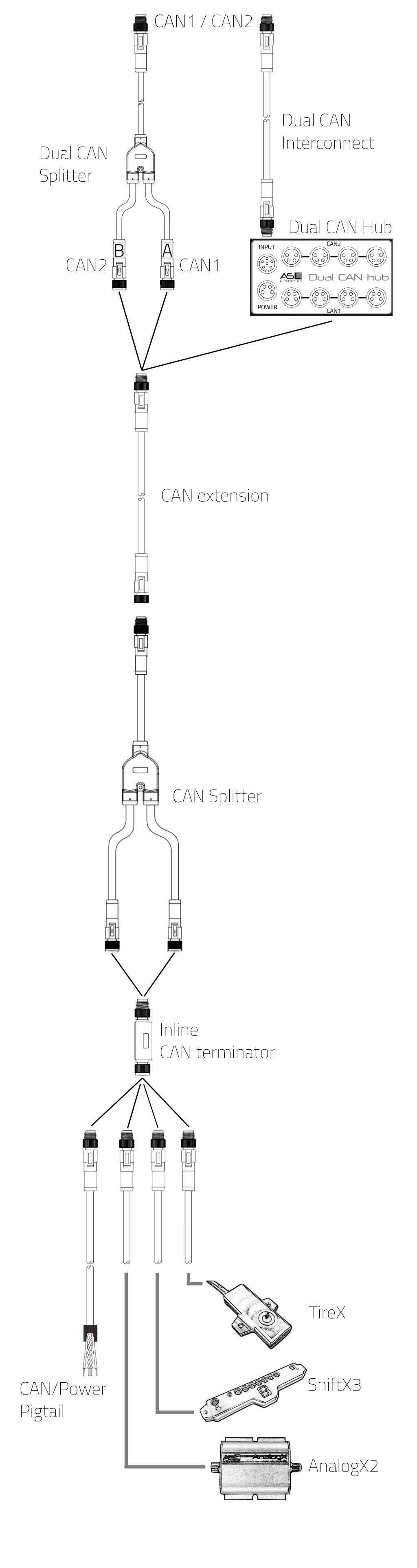
CAN bus Harness
The plug and play CAN bus harness system lets you easily connect CAN bus devices to your RaceCapture or PodiumConnect system, without the need to splice, crimp, or heat-shrink connections. Multiple-length extension cables lets you build a harness that perfectly matches your installation needs.
Click on the items within the image to see details.

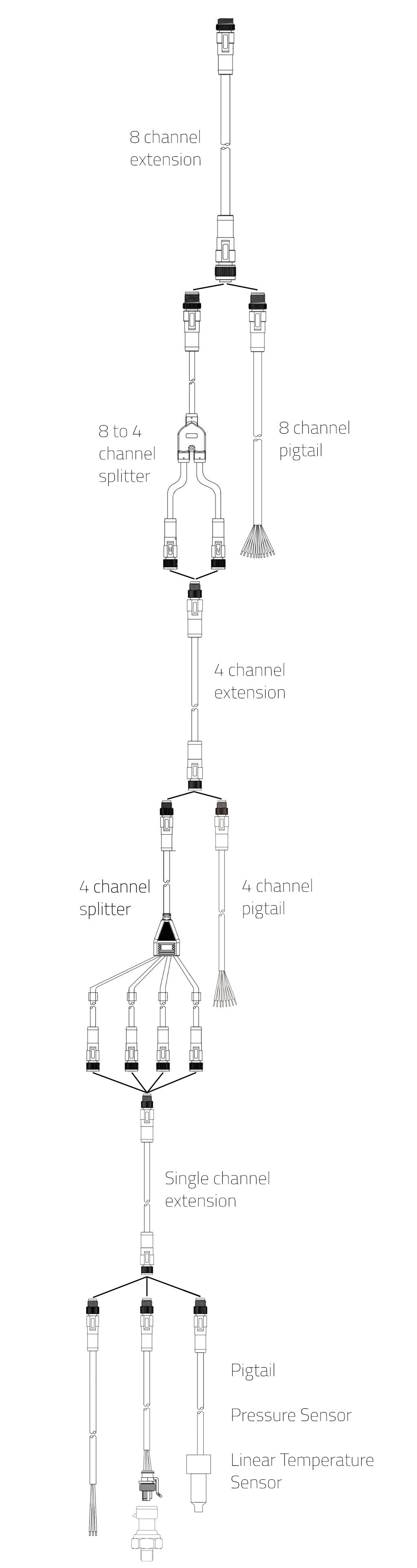
Analog harness
The plug and play Analog/Digital harness system lets you easily connect individual sensors to your RaceCapture system, without the need to splice, crimp, or heat shrink connections. Multiple-length extension cables for each level lets you build a harness that perfectly matches your installation needs.
- Note: The same 8 channel connector (and downstream connectors) can plug into an M12-12P analog port or the M12-12P digital port of the system.
Click on the items within the image to see details.

CAN bus harness components
Dual CAN splitter
M8-6P male to dual M8-4P female splits CAN1/CAN2 into individual CAN1 and CAN2 connections. Product Info
Limited power (1A @ 12v) is provided to devices connected to CAN1 and CAN2. For higher power requirements, please use the Powered Dual CAN Hub
- A connection: connects to CAN1
- B connection: connects to CAN2


Dual CAN interconnect
M8-6P male to M8-6P male link cable for connecting two CAN bus networks to our Powered Dual CAN Hub. 1 meter length. Product Info


Powered dual CAN hub
Powered CAN hub featuring 8 ports (4 ports for CAN1 and 4 ports for CAN2). Use with the Dual CAN interconnect cable to link to your RaceCapture or PodiumConnect system. Product Info

CAN extension
M8-4P male to M8-4P female cable extends a CAN bus network. Available in 0.5, 1, 2, 3, and 4 meter lengths. Product Info
- Power rated at 1A (12watts at 12v)


CAN splitter
M8-4P male to dual M8-4P splits a single CAN bus so a device can be inserted in the middle of a CAN bus network.
- Note: stub length to devices should be about 300mm maximum, including length of Y adapter branch.
The Y adapter includes a 15cm feed connection with a M8 4P male connector, with two 10cm connections with M8 4P female connectors on each end, wired in parallel.


Inline CAN terminator
M8-4P male to M8-4P female inline 120 ohm CAN terminator - place one near end of the CAN bus network to ensure signal integrity. Product Info
- Note: Only one terminator should be used at the end of the network/cable-run.


Power CAN pigtail
M8-4P male to pigtail for connecting custom device to the Plug and Play cabling system, or for powering a RaceCapture or PodiumConnect system. 2 meter length. Product Info
| Pin | Color | Connection |
|---|---|---|
| 1 | White | CAN low |
| 2 | Red | 9-24v / 1A (~12W) |
| 3 | Green | CAN high |
| 4 | Black | Ground |


CAN+power for device
M8-4P female to pigtail for a custom-wired non Plug and Play connection to one of our CAN bus enabled devices such as TireX, AnalogX2, or ShiftX3 Product Info
| Pin | Color | Connection |
|---|---|---|
| 1 | White | CAN low |
| 2 | Red | 9-24v / 1A (~12W) |
| 3 | Green | CAN high |
| 4 | Black | Ground |


Analog / Digital harness components
8 channel extension
Male to Female M12 12P cable extends 8 analog or digital channels. Available in 1 or 2 meter lengths. View Product


8 to 4 channel splitter
M12-12P male to dual M8-8P female connector splits 8 analog or digital channels into dual 4 channel connections. Product Info


8 channel pigtail
M12-12P 0.3 meter male pigtail breaks out 8 analog or digital channels. Product Info
- 24 AWG
| Pin | Color | Connection | Analog Mapping | Digital Mapping |
|---|---|---|---|---|
| 1 | Blue | Analog/Digital B1 | Analog 5 | GPIO 1 |
| 2 | Yellow | Analog/Digital B2 | Analog 6 | GPIO 2 |
| 3 | Green | Analog/Digital B4 | Analog 8 | GPIO 4 |
| 4 | Pink | Analog/Digital A1 | Analog 1 | Timer/RPM 1 |
| 5 | White | Analog/Digital A2 | Analog 2 | Timer/RPM 2 |
| 6 | Red | Vref | 5v @ 0.5A | 5v @ 0.5A |
| 7 | Violet | Analog/Digital A3 | Analog 3 | Timer/RPM 3 |
| 8 | Orange | Analog/Digital A4 | Analog 4 | Timer/RPM 4 |
| 9 | Light Green | Analog/Digital B3 | Analog 7 | GPIO 3 |
| 10 | Grey | Ground | ||
| 11 | Brown | Ground | ||
| 12 | Black | Ground |


4 channel extension
M8-4P male to M8-4P female cable extends 4 analog or digital channels. Available in 1 and 2 meter lengths. Product Info


4 channel pigtail
M8-8P male pigtail for 4 analog or digital channels. 1 meter length. Product Info
- 24 AWG
| Pin | Color | Connection |
|---|---|---|
| 1 | White | Analog/Digital 1 |
| 2 | Yellow | Analog/Digital 2 |
| 3 | Grey | Analog/Digital 4 |
| 4 | Red | 5v reference |
| 5 | Brown | Ground |
| 6 | Pink | 5v reference |
| 7 | Blue | Analog/Digital 3 |
| 8 | Green | Ground |


4 channel splitter
M8-8P Male splits 4 analog or digital channels into 4 M8-3P female connections. Product Info


Single channel extension
M8-3P male to M3-3P female extends a single analog or digital channel. Available in 1, 2, 3, and 4 meter lengths. Product Info


Single channel pigtail
M8-3P male pigtail for a single analog or digital connection. 2 meter length. Product Info
- 24 AWG
| Pin | Color | Connection |
|---|---|---|
| 1 | Brown | Ground |
| 3 | Blue | 5v |
| 4 | Black | Signal Input |


Pressure sensor
M8-3P male to 3 pin Delphi GT150 pressure sensor connector. 2 meter length. 10 bar/150 PSI Product Info 150 bar/2175 PSI Product Info
| M8 Pin | GT150 Pin | Connection |
|---|---|---|
| 1 | A | Ground |
| 3 | B | 5v Power |
| 4 | C | Signal |


Linear temperature sensor
M8-3P male to linear temperature sensor. 2 meter length. Product Info


Standard connectors and pinouts
The following represents connector and pinout standard for power, CAN, and analog/digital signaling
Interconnects are based on industry-standard M8 and M12 connectors
Power + CAN Single interconnect
- Connector: M8 4P, A coding

Male connector pictured
| Pin | Connection | Notes |
|---|---|---|
| 1 | CAN low | White |
| 2 | Power | Red, 9-24v / 1A (~12W) |
| 3 | CAN high | Green |
| 4 | Ground | Black |
Power is standard automotive 12-14v (nominal).
The M8 is an industry standard connector; field-wireable connectors for the M8 4P and other variants are available from 3rd parties:
- Male: Straight | Right angle
- Female: Straight | Right angle
Dual CAN + power interconnect
- Connector: M8 6P, A coding

Male connector pictured
| Pin | Connection | Notes |
|---|---|---|
| 1 | CAN1 low | |
| 2 | CAN2 low | |
| 3 | CAN2 high | |
| 4 | Ground | |
| 5 | CAN1 high | |
| 6 | Power | 9-24v / 1A (~12W) |
Single analog/digital channel
- Connector: M8 3P, A coding

Male connector pictured
| Pin | Connection | Notes |
|---|---|---|
| 1 | Ground | Brown |
| 3 | Power | Blue (5v @ 1A max) |
| 4 | Signal | Black |
Quad analog/digital channels
- Connector: M8 8P Male, A coding

| Pin | Connection | Notes |
|---|---|---|
| 1 | Analog/Digital 1 | |
| 2 | Analog/Digital 2 | |
| 3 | Analog/Digital 4 | |
| 4 | Vref | 5v @ 1A max current, combined with pin 6 |
| 5 | Ground | |
| 6 | Vref | 5v @ 1A max current, combined with pin 4 |
| 7 | Analog/Digital 3 | |
| 8 | Ground |
Octo analog/digital channels
- Connector: M8 12P, A coding

Male connector pictured
| Pin | Connection | Analog Mapping | Digital Mapping |
|---|---|---|---|
| 1 | Analog/Digital B1 | Analog 5 | GPIO 1 |
| 2 | Analog/Digital B2 | Analog 6 | GPIO 2 |
| 3 | Analog/Digital B4 | Analog 8 | GPIO 4 |
| 4 | Analog/Digital A1 | Analog 1 | Timer/RPM 1 |
| 5 | Analog/Digital A2 | Analog 2 | Timer/RPM 2 |
| 6 | Vref | 5v @ 0.5A | 5v @ 0.5A |
| 7 | Analog/Digital A3 | Analog 3 | Timer/RPM 3 |
| 8 | Analog/Digital A4 | Analog 4 | Timer/RPM 4 |
| 9 | Analog/Digital B3 | Analog 7 | GPIO 3 |
| 10 | Ground | ||
| 11 | Ground | ||
| 12 | Ground |