Ford EDIS technical information
Ford EDIS general information
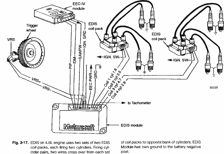
The Ford EDIS system consists of a controller module, coil packs, a crank trigger wheel and matching variable reluctance sensor. Running alone, the EDIS module will fire the spark plugs at 10 degrees BTDC, operating in it's "limp home mode".
Normal operation involves interaction between the engine management system and the EDIS module, using the PIP and SAW as communication lines. After each ignition event, the EDIS module requests the current ignition advance value from the engine management unit using the PIP line. The engine management system calculates the current ignition advance and signals it back on the SAW input of the EDIS module. To communicate the advance value, the SAW reply signal is a pulse with a duration that corresponds to the amount of degrees advance.
The formula for calulating the SAW pulsewidth is as follows:
SAW Pulse width (uSec) = 1536 - (25.6 x (desired spark advance in degrees))
Range: 64 - 1792us (57.5° BTDC to 10° ATDC)
Resolution: 4us (5/32nd of a degree)
The MegaJolt Lite Jr emulates the Ford engine management system, communicating the desired ignition advance value to the EDIS module calculated from it's internal configuration.
Trigger wheel and sensor mounting
Each EDIS application requires a different sensor mounting configuration. Use the following table to determine the correct sensor position in relation to the missing tooth and the engine's TDC.
| Type | Degrees BTDC |
|---|---|
| EDIS-4 | 90 |
| EDIS-6 | 60 |
| EDIS-8 | 50 |
With the Engine at TDC for cylinder #1, the sensor should be positioned 'N' degrees before the missing tooth. Make sure you take into account the rotation of the engine: clockwise or counter-clockwise when determining your sensor mounting.
For example: On an EDIS-4 application with the engine at Top Dead Center (TDC) - if the missing tooth is aligned with TDC (pointing up, or aligned with the crank pulley key), the sensor should be aligned with the center of the tooth 90 degrees BTDC. If this was a typical clockwise rotating engine, the sensor would be positioned 90 degrees to the left side of the crank sensor (9 o'clock position), when viewed facing the crank.
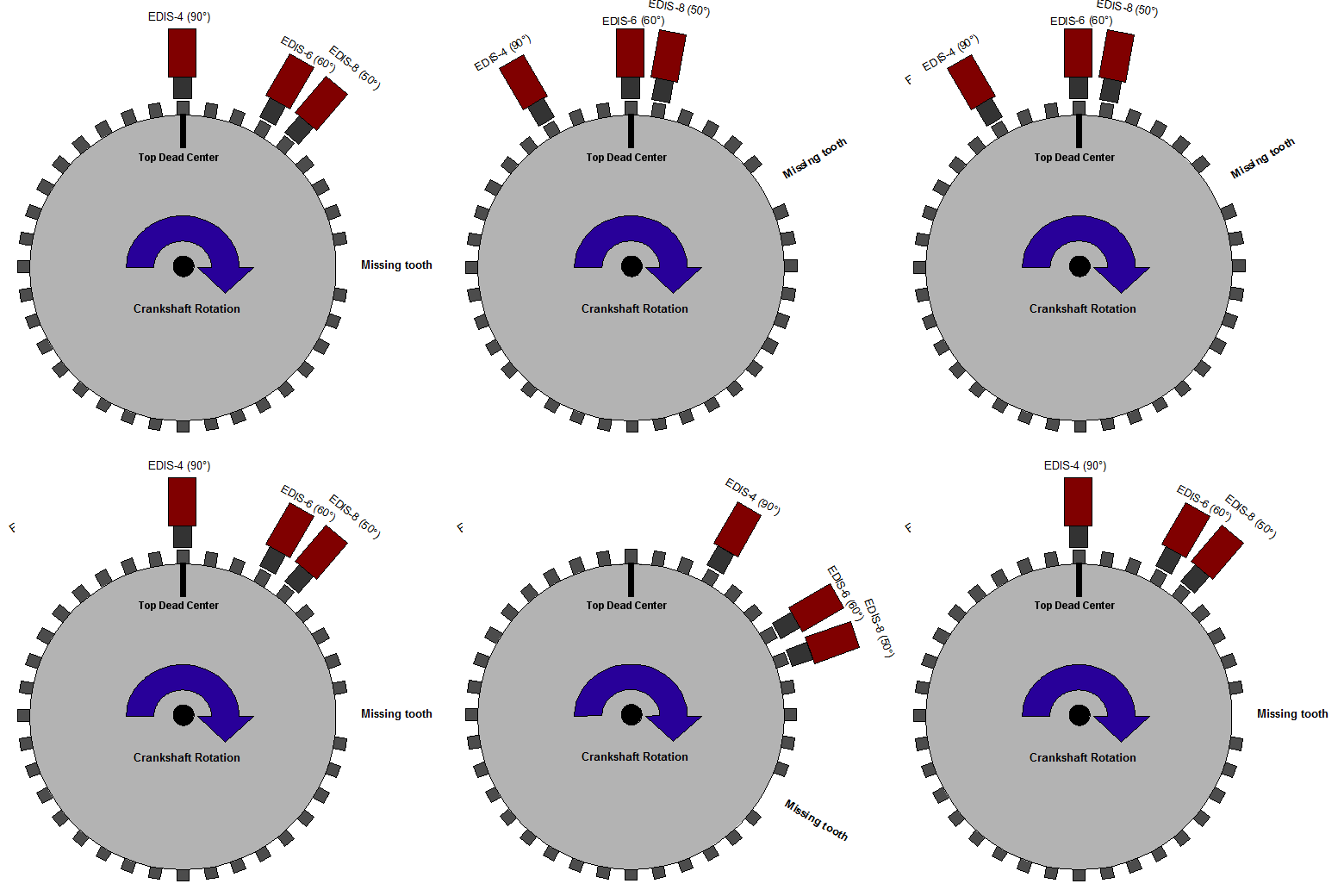
Shown: Relationship between engine Top Dead Center and sensor positioning. Wherever you place the sensor, the distance from the missing tooth must remain constant.
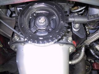
As long as the relation between the missing tooth and sensor remains constant, you can position the sensor at your convenience. In my case with a toyota 4AG motor, it was easier to mount the sensor on the exhaust side of the block, so I oriented the missing tooth so it pointed down, or opposite, of TDC. The sensor was still mounted 90 degrees BTDC, at the 3 o'clock position when facing the crank.
Interfacing with OEM Tach
Many OEM tachometers operate by sensing a high voltage kickback pulse from the coil. You can find out if you have one of these tachometers by connecting your auto's tach input to the MJLJ tach output. If you don't see activity on on the gauge then it is likely that your unit requires this HV kickback pulse.
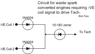
If you are converting from single-coil distributor setup, your OEM tach will need to see the HV kickback pulse from both EDIS coil packs. Here's a simple circuit on how to extract both coil pack's HV pulse while maintaining electrical isolation.
Trigger Wheel Designs
Adapting OEM trigger wheel
The most common approach is to obtain a pre-machined trigger wheel, usually sourced from an OEM application, and then mate that with the crank pulley for the destination engine.
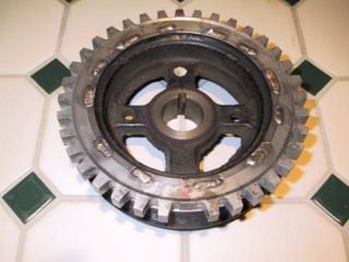
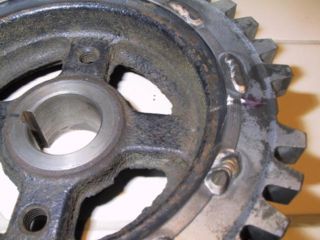
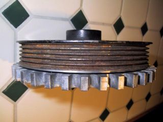
Sometimes, part of the existing crank pulley can be machined down to fit the OEM trigger wheel. the following example mates a trigger wheel from a 1997 Ford Escort 1.9L to a crank pulley for a Toyota 4AG motor.
The pulley started off with two rows of belts; the inner to drive the water pump and alternator, and the outer to drive the air-conditioning system. Since the air conditioning system was removed from the vehicle, the unused outer section was carefully machined down until the trigger wheel could slip into place. The trigger wheel was then rotated into alignment and then welded into place.
Trigger Wheel Designs by Vehicle
- See the Trigger Wheel Designs page for examples of different Trigger Wheel installations.
Alternate coil wiring
Multiple coil primaries per driver
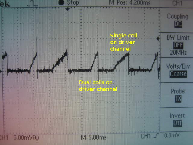
The oscilloscope plot illustrates the current consumption of a typical EDIS-4 ignition system. In this test, a 100mV/100A shunt was used to measure current consumption for both coil drivers. Of the two coil drivers, one was wired with two coil primaries in parallel, and the other connected as normal to a s single coil primary.
The plot illustrates the effects of active current limiting- a 'feature' of the Ford EDIS module. The EDIS module will automatically adjust dwell time to charge the coil primary up to the pre-determined current limit.
The coil driver wired with two primaries shows 1/2 the dwell time of the other coil driver, which is wired normally with one coil primary.

