RaceCapturePro2 hardware guide: Difference between revisions
No edit summary |
|||
| (7 intermediate revisions by the same user not shown) | |||
| Line 8: | Line 8: | ||
===Power Connection=== | ===Power Connection=== | ||
====Via terminal block==== | |||
Connect RaceCapture/Pro to a power source between 9 and 18V. To fully support all devices and outputs, provide at least a 5A fused connection. | Connect RaceCapture/Pro to a power source between 9 and 18V. To fully support all devices and outputs, provide at least a 5A fused connection. | ||
====Via RJ45 connection==== | |||
You can also power via the RJ45 connector: | |||
[[File:Canrj45.png]] | |||
* '''Important note''' The +12v connection on the RJ45 is connected internally to the +12v on the terminal block on RaceCapture/Pro MK2. It's recommended you only power via one source - RJ45 or terminal block - if you have both connected at the same time, you may cause back-feeding of power through RaceCapture/Pro, which may cause damage to the unit. | |||
==Sensors== | ==Sensors== | ||
| Line 39: | Line 47: | ||
====Connection==== | ====Connection==== | ||
Typically this involves connecting a single wire between one of RaceCapture/Pro's analog inputs and the sensor wire. | Typically this involves connecting a single wire between one of RaceCapture/Pro's analog inputs and the sensor wire. | ||
* '''Important'': when tapping into existing sensors that are wired into an existing gauge or ECU, '''do not''' connect an additional pull-up resistor. The existing gauge or system already provides whatever circuitry is needed to drive the sensor. | * '''Important''': when tapping into existing sensors that are wired into an existing gauge or ECU, '''do not''' connect an additional pull-up resistor. The existing gauge or system already provides whatever circuitry is needed to drive the sensor. | ||
====Calibration==== | ====Calibration==== | ||
To successfully map these sensors you will need information from the manufacturer on the sensor (gauge) specifications, or, if not available, take direct measurements across the range of the gauge. | To successfully map these sensors you will need information from the manufacturer on the sensor (gauge) specifications, or, if not available, take direct measurements across the range of the gauge. | ||
First, you will need to determine the '''voltage curve'': You will need to know if the sensor responds linearly or on a curve. | First, you will need to determine the '''voltage curve''': You will need to know if the sensor responds linearly or on a curve. | ||
=====Linear===== | =====Linear===== | ||
| Line 51: | Line 59: | ||
Example: Tapping into an existing pressure gauge: | Example: Tapping into an existing pressure gauge: | ||
0 PSI = 0.5 v | * 0 PSI = 0.5 v | ||
150 PSI = 4.5 volts | * 150 PSI = 4.5 volts | ||
You would adjust the analog mapping to set the scale so that: 0.5 volts = 0 PSI and 4.5 volts = 150 PSI | You would adjust the analog mapping to set the scale so that: 0.5 volts = 0 PSI and 4.5 volts = 150 PSI | ||
| Line 59: | Line 67: | ||
=====Curved response===== | =====Curved response===== | ||
Thermistor-based temperature sensors typically will have a curved response. This is more complex to map, but RaceCapture/Pro offers the ability map multiple points across this curve, | Thermistor-based temperature sensors typically will have a curved response. This is more complex to map, but RaceCapture/Pro offers the ability map multiple points across this curve, and will linearly interpolate between points. | ||
As the sensor's temperature, pressure (or whatever the sensor is reading) rises, the voltage sensed may increase | As the sensor's temperature, pressure (or whatever the sensor is reading) rises, the voltage sensed may increase or decrease. Use the manufacturer's specifications to map these values into the analog sensor configuration. If you do not have the manufacturer's specifications, you will need to take voltage readings across the range of the sensor. | ||
[[image:curved_response_sensor.png|500px]] | [[image:curved_response_sensor.png|500px]] | ||
| Line 96: | Line 104: | ||
The RJ45 connector to the right of the terminal block connects CAN bus 1 and 2. | The RJ45 connector to the right of the terminal block connects CAN bus 1 and 2. | ||
* See the quick reference guide for pinout | * See the quick reference guide for pinout | ||
====CAN Termination==== | |||
RaceCapture/Pro MK2 has built-in CAN termination on both ports. | |||
=====Disabling CAN termination===== | |||
Disabling CAN termination requires modification of the circuit board. The process is different based on the revision of the board: | |||
* '''Identifying board revision:''' The board revision is located to the left of the SD card slot, in the lower left corner of the main circuit board. | |||
* '''Revision J Boards''': | |||
Disabling termination involves removal of the 120 ohm surface mount resistors corresponding to each CAN channel. The resistor can be removed by using a soldering iron tip and applying heat to both side of the resistor until the solder melts and the resistor slides off of the pad. | |||
** '''CAN 1''': Remove resistor R16, below the RJ45 port | |||
** '''CAN 2''': Remove resistor R21, below the RJ45 port. | |||
* '''Revision K boards''': | |||
Disabling termination on Revision K boards involves breaking a PCB trace jumper for the corresponding CAN channel. The best way is to use the edge of a small jeweler's or precision screwdriver blade to scratch the trace away until you can clearly see the trace has been broken. | |||
** '''CAN 1''': Break the trace on the jumper pad above and to the left of R16, | |||
** '''CAN 2''': Break the trace on the jumper pad above and to the left of R21 | |||
=====Restoring CAN termination===== | |||
To restore CAN termination, you can have the following options: | |||
* Add an external 120 ohm, 1/4W resistor as closely as possible to the RJ45 connector | |||
* Revision K board: apply solder to re-bridge the jumpers that were previously broken. | |||
* Revision J board: Re-solder a 0603 resistor to the R16 or R21 pads, depending on the CAN channel needing termination. | |||
===SD Card Slot=== | ===SD Card Slot=== | ||
Latest revision as of 00:04, 9 August 2017
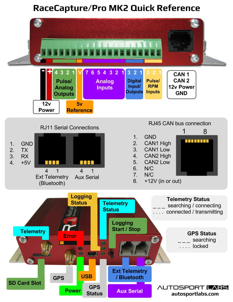
Quick Reference
Download a printable PDF
Connections
Power Connection
Via terminal block
Connect RaceCapture/Pro to a power source between 9 and 18V. To fully support all devices and outputs, provide at least a 5A fused connection.
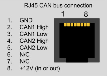
Via RJ45 connection
You can also power via the RJ45 connector:
- Important note The +12v connection on the RJ45 is connected internally to the +12v on the terminal block on RaceCapture/Pro MK2. It's recommended you only power via one source - RJ45 or terminal block - if you have both connected at the same time, you may cause back-feeding of power through RaceCapture/Pro, which may cause damage to the unit.
Sensors
Also see the Comprehensive Sensor installation guide
Analog Inputs 1-7
Specifications
- RaceCapture/Pro has 8 analog inputs; the 8th input is wired internally to measuring battery voltage.
- Analog input range is 0 - 5v
- Input Impedance: 1 megaohm
Active Sensors/Signals
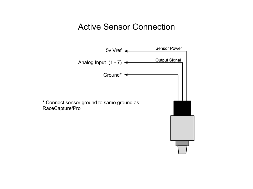
The Analog Input Channels accept a 0-5v input signal (protected up to 400V). Connect the input from a sensor to the appropriate connection of the terminal block.
Resistive sensor
When connecting resistive style sensors, like many temperature and pressure sensors, one terminal of the sensor is connected to ground, and the other is connected to the Analog input, with a pullup resistor connected to the +5V Voltage Reference on the terminal block. A 2.2K resistor is recommended for most applications.

5V Voltage Reference
This output provides a 5V reference to be used with the Analog Inputs. Up to 1A is provided to supply power to active sensors, pull-up resistors and other purposes. This reference output is protected against short-circuits with an auto-resetting fuse. If the fuse is active, a low or zero voltage reading may be observed on this port. To verify an over-current situation, test the voltage on the port without any load connected.
Analog Calibration
Channels can be calibrated based on linear formula or linearly interpolated mapping. See the Sensor Installation Guide for more information on calibrating sensors.
Tapping into existing Sensors
Sometimes, you may want to tap into existing sensors, such as one driving existing gauges, or sensors feeding the ECU.
Connection
Typically this involves connecting a single wire between one of RaceCapture/Pro's analog inputs and the sensor wire.
- Important: when tapping into existing sensors that are wired into an existing gauge or ECU, do not connect an additional pull-up resistor. The existing gauge or system already provides whatever circuitry is needed to drive the sensor.
Calibration
To successfully map these sensors you will need information from the manufacturer on the sensor (gauge) specifications, or, if not available, take direct measurements across the range of the gauge.
First, you will need to determine the voltage curve: You will need to know if the sensor responds linearly or on a curve.
Linear
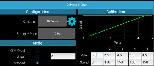
- If the sensor response is linear, then you will need to know just two points: the voltage at the low end of the gauge, and the voltage at the high end of the gauge.
Example: Tapping into an existing pressure gauge:
- 0 PSI = 0.5 v
- 150 PSI = 4.5 volts
You would adjust the analog mapping to set the scale so that: 0.5 volts = 0 PSI and 4.5 volts = 150 PSI
Curved response
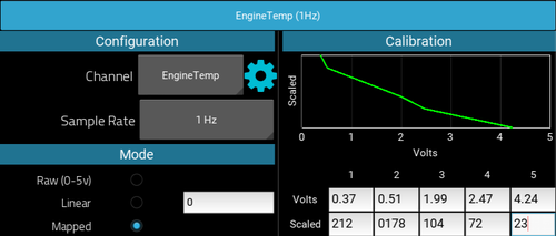
Thermistor-based temperature sensors typically will have a curved response. This is more complex to map, but RaceCapture/Pro offers the ability map multiple points across this curve, and will linearly interpolate between points.
As the sensor's temperature, pressure (or whatever the sensor is reading) rises, the voltage sensed may increase or decrease. Use the manufacturer's specifications to map these values into the analog sensor configuration. If you do not have the manufacturer's specifications, you will need to take voltage readings across the range of the sensor.
Calibrating Battery voltage channel
The 8th channel is dedicated to battery voltage. This calibration is set at the factory, but you can fine tune the calibration by editing the mapped value in the analog configuration view for the Battery channel.
- The default calibration value is 1.0 - you can adjust it up or down to fine tune to match your electrical system.
General Input/Output Channels 1 - 3
Depending on configuration, these channels can accept either a digital input, or provide an output to control external devices.
- When configured for input, the channel accepts a 0-5v input (protected up to 400V).
- When configured for output, the channel provides an open-drain output that can drive 1A and is thermal / over-current protected with inductive load clamping.
Frequency/Pulse Input 1 - 3
These input channels can be used to time the duration between digital pulses for purposes of measuring RPM, shaft speed, and so on. The input accepts 0-12V (protected up to 400V)
TACH SIGNAL NOTES
Do not connect the old-style tachometer signal directly to RaceCapture/Pro. This signal is typically sourced from a wire that connects directly to the (-) post of the ignition coil. These signals are 400-500v peak and can damage your RaceCapture/Pro hardware.
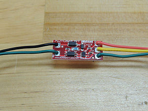
You can use the CoilX sensor module to safely interface this high voltage RPM signal. See the CoilX page for more information.
Newer style tach signals sourced from the ECU will likely provide a clean square wave signal and can be connected directly to this input.
If unsure, observe the signal with an oscilloscope and/or consult technical documentation of your vehicle.
CAN bus port
The RJ45 connector to the right of the terminal block connects CAN bus 1 and 2.
- See the quick reference guide for pinout
CAN Termination
RaceCapture/Pro MK2 has built-in CAN termination on both ports.
Disabling CAN termination
Disabling CAN termination requires modification of the circuit board. The process is different based on the revision of the board:
- Identifying board revision: The board revision is located to the left of the SD card slot, in the lower left corner of the main circuit board.
- Revision J Boards:
Disabling termination involves removal of the 120 ohm surface mount resistors corresponding to each CAN channel. The resistor can be removed by using a soldering iron tip and applying heat to both side of the resistor until the solder melts and the resistor slides off of the pad.
- CAN 1: Remove resistor R16, below the RJ45 port
- CAN 2: Remove resistor R21, below the RJ45 port.
- Revision K boards:
Disabling termination on Revision K boards involves breaking a PCB trace jumper for the corresponding CAN channel. The best way is to use the edge of a small jeweler's or precision screwdriver blade to scratch the trace away until you can clearly see the trace has been broken.
- CAN 1: Break the trace on the jumper pad above and to the left of R16,
- CAN 2: Break the trace on the jumper pad above and to the left of R21
Restoring CAN termination
To restore CAN termination, you can have the following options:
- Add an external 120 ohm, 1/4W resistor as closely as possible to the RJ45 connector
- Revision K board: apply solder to re-bridge the jumpers that were previously broken.
- Revision J board: Re-solder a 0603 resistor to the R16 or R21 pads, depending on the CAN channel needing termination.
SD Card Slot
The SD card slot is used to store datalogging sessions. 512MB to 32GB cards are supported.
USB Port
Used for system configuration and monitoring
LED Indicators
- Power LED
Indicates the unit is powered up (via 12v supply or USB)
- GPS LED
Indicates GPS Activity. Slow flash (1Hz) indicates GPS is actively acquiring. Fast flash (5 times per second) indicates GPS is locked on to satellites.
- Logging LED
Indicates SD card Logging Activity. The flash rate matches the channel with the highest configured logging rate.
- Telemetry LED
Indicates telemetry activity.
- A slow flash interval indicates connection initialization
- A regular flash matching the highest logging rate (up to 10Hz) indicates connected and streaming
Pushbutton
Press to manually start / stop a logging session. Logging LED will indicate logging activity.
- Note this may be overridden by any on-board scripts that may automatically start or stop logging.
Communication Ports
The communication ports a standard RS232 serial connection with power (up to 5v at 1.5A)
- Ext Telemetry / Bluetooth - Used for Bluetooth module
- Auxiliary port - used for integrating external systems / devices
- On-board Lua Scripting can be used to customize integrations with external devices
GPS port
Connect the GPS antenna to this port.
- Tighten this to 3-5 inch/lbs. This connection should be snug.
- To prevent damage to the connector, do not over-tighten
Telemetry port
If installed, connect the telemetry antenna to this port.
- Tighten this to 3-5 inch/lbs. This connection should be snug.
- To prevent damage to the connector, do not over-tighten
Physical Installation
- Dimensions: 5.3" (width) x 4.2" (height) x 1.2" (tall) / 135x110x31 mm(est)
- Mounting area: 5.5"(140mm) x 4"(102mm)
- Mounting fasteners: Dual mounting points on 5" (127mm) centers - 0.125"-0.25" (3-6mm) fastener
Mounting orientation and position
The ideal mounting position for RaceCapture/Pro is mounted flat (right side up or upside down), in the exact center of the vehicle. This gives the best effect from the built in Gyros, which measures Yaw (understeer / oversteer), Pitch (braking / acceleration rotation) and roll (side-side rotation)
Shock isolation mounting
In very harsh environments you may want to mount RaceCapture/Pro using rubber isolators. Info on isolation mounts
Default Accelerometer Configuration
The default accelerometer configuration assumes RaceCapture/Pro is mounted flat, right side up with the terminal block pointed towards the front of the vehicle. Other orientations are supported by changing the settings in the RaceCapture App configuration.

