MJLJ V4 vehicle installation guide: Difference between revisions
| Line 137: | Line 137: | ||
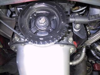
[[Image:timing_wheel_mounted.jpg|Modified crank pulley mounted with VR Sensor|320px]] | [[Image:timing_wheel_mounted.jpg|Modified crank pulley mounted with VR Sensor|320px]] | ||
---- | ---- | ||
===Trigger Wheel Designs by Vehicle=== | ===Trigger Wheel Designs by Vehicle=== | ||
* See our [[Trigger Wheel Designs]] Page for more information on vehicle specific installations. | * See our [[Trigger Wheel Designs]] Page for more information on vehicle specific installations. | ||
Revision as of 23:22, 8 January 2010
System Overview
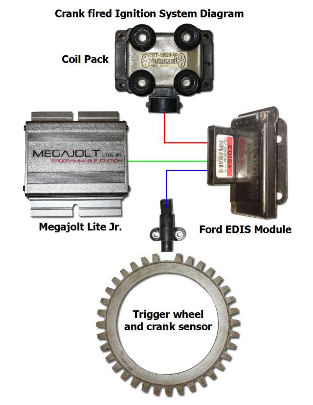
The following illustrates the essential components of a Megajolt-powered crank fired ignition system, and their relationships. Once you perform the necessary mechanical installation of the crank trigger wheel and sensor, the rest is a straightforward wiring process.
Parts you will need
To complete your installation, you will need the following components.
- Megajolt Lite Jr. Ignition Controller: Purchase here
- EDIS module: Acquire an EDIS Ignition module matching your engine type- EDIS-4 for 4 cylinder engines; EDIS-8 for 8 cylinders; EDIS-6 for 6 cylinders.
Due to the high cost for new replacement, EDIS modules are almost always sourced from donor vehicles. Most can be harvested from automotive salvage yards, acquired on ebay, or sourced from online vendors.
| Type | Donor Vehicle | Years | Market |
|---|---|---|---|
| EDIS-4 | Ford Escort | 1990-99 | US |
| Ford Fiesta | 1990-99 | Europe | |
| Mazda 121 | 1996-2001 | Europe | |
| Ford Escort | 1990-2000 | Europe | |
| Ford Sierra | 1990-93 | Europe | |
| EDIS-6 | Ford Ranger Pickup truck | 1990-97 | US |
| Mazda B-Series Pickup | 1990-97 | US | |
| Ford Explorer | 1990-97 | US | |
| Mazda Navajo | 1990-97 | US | |
| Ford Aerostar | 1990-97 | US | |
| Ford Scorpio 2.9 Cosworth | 1996-97(?) | Europe | |
| Ford Mondeo V6 | 1993-1996(?) | Europe | |
| EDIS-8 | Crown Victoria | 1990-97 | US |
| Mercury Grand Marquis | 1990-97 | US | |
| Lincoln Town Car | 1990-97 | US | |
| Ford Thunderbird | 1990-97 | US | |
| Mercury Cougar | 1990-97 | US | |
| Ford Mustang 5.0 | 1990-97 | US |
- Coil packs: Many use the matching Ford coil packs, but typically most OEM coil packs that closely matches the ford EDIS primary(about 0.5 ohms) and secondary(11-13K ohms) DC coil resistance should work fine. Source from donor vehicle, or can be purchased new for a reasonable cost.
- Crank Sensor: We suggest you use a Ford OEM crank sensor- also known as a 'VR (Variable Reluctance) Sensor'- this guarantees best compatibility with the Ford EDIS module. Typically sourced from donor vehicle, or may be purchased new from an auto parts retailer at a low cost (about $20 USD)
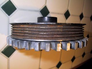
- Trigger wheel: The Ford EDIS module requires a 36 tooth wheel with one missing tooth- commonly referred to as a 36-1 wheel. Many adapt the trigger wheel removed from the crank pulley of the donor engine. For example, the Ford Escort 1.9L motor has a crank pulley with a pressed-on ring-shaped trigger wheel when removed, yields a convenient part that can be adapted to the receiving engine. Others machine the pattern directly into the existing crank pulley, fabricate a custom wheel, or purchase a wheel ready made for their engine.
- Component Suppliers
The following partner companies offer Ford EDIS Modules and related components:
| Location | Company |
|---|---|
| USA | Boost Engineering |
| UK | Trigger Wheels |
EDIS installation
Crank timing wheel and sensor installation
The Ford EDIS ignition module is designed to work with a 36 tooth wheel, with 1 missing tooth to act as a synchronization reference for engine Top Dead Center.
When mounting the sensor wheel the EDIS module requires specific positioning of the sensor relative to the missing tooth, while the engine is at Top Dead Center. The following table defines the sensor position relative to the missing tooth for 4,6 and 8 cylinder EDIS modules.
| Type | "N" Degrees BTDC | "N" Teeth |
|---|---|---|
| EDIS-4 | 90 | 9 |
| EDIS-6 | 60 | 6 |
| EDIS-8 | 50 | 5 |
Align the sensor and timing wheel so the missing tooth passes the sensor N degrees before the crank reaches Top Dead Center (TDC) for cylinder #1.
Note: Since the sensor wheel has a tooth every 10 degrees, "N" degrees is equivalent to N / 10 teeth.
A simple installation procedure to follow:
- Mount the sensor in any convenient way that simplifies bracket design and accommodates mounting points on the engine block.
- Turn the crankshaft to precise Top Dead Center (TDC) for cylinder #1.
- Position the timing wheel onto the crank pulley with the missing tooth aligned to the sensor.
- Now offset the the timing wheel position:
- If your engine turns clockwise when facing the crank pulley, rotate the timing wheel clockwise "N" Teeth.
- If your engine turns counter-clockwise when facing the crank pulley, rotate the timing wheel counter-clockwise "N" Teeth.
- mark this final location of the sensor wheel onto the crank pulley- then weld or bolt timing wheel into place as appropriate.
The following graphic illustrates how the offset between the sensor and missing tooth remains the same independent from engine TDC. If you keep this in mind, you can mount the sensor in any way that is robust and convenient.
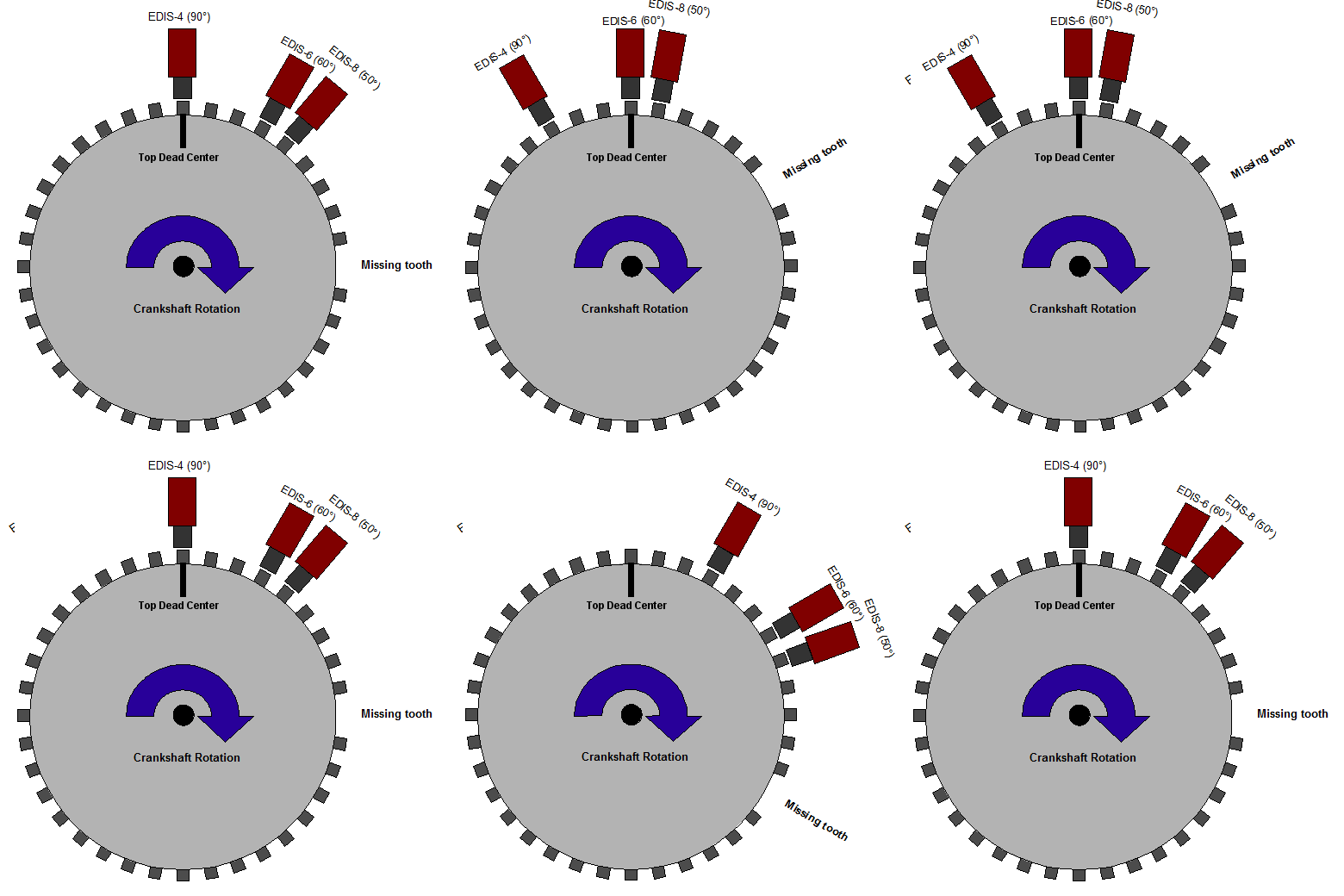
Shown: Relationship between engine Top Dead Center and sensor positioning. Wherever you place the sensor, the distance from the missing tooth must remain constant.
Typical Trigger Wheel Installation
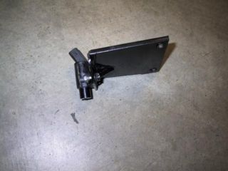
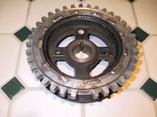
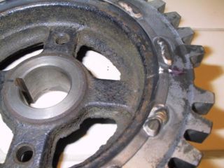
The following photos illustrate an EDIS-4 installation on a Toyota 4AG engine. Notice the thickness of the sensor bracket designed to minimize harmonic vibrations which may affect the sensor signal. The crank pulley was machined down to accommodate the timing wheel from a 1997 Ford Escort, and then tack welded in place.
Trigger Wheel Designs by Vehicle
- See our Trigger Wheel Designs Page for more information on vehicle specific installations.
- Also visit our Forums for the latest designs developed by our community members.
EDIS and coil-pack installation
Since the EDIS module can operate the engine by itself in a "limp-home" mode, with the advance fixed at 10 degrees BTDC, it's recommended you install the EDIS module and coil packs first, and then verify your engine runs before wiring in the MJLJ.
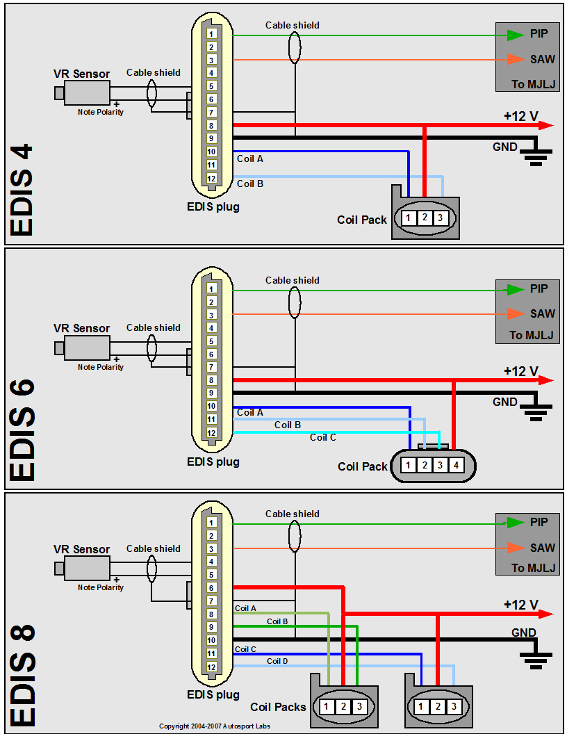
Wire up the EDIS module and coil pack(s) using the following diagram, matching your engine type (EDIS 4 = 4 cylinder, EDIS 6 = 6 cylinder, EDIS 8 = 8 cylinder). Engines with 'even-fire' configurations are supported, which represents the vast majority of 4,6, and 8 cylinder engines in production.
EDIS Wiring notes and guidelines
- Use shielded cable for the VR Sensor. Be sure to ground the shield as well. A 22-24 gauge, 2 conductor cable with a foil shield works well.
- Use 12-14 gauge wire for EDIS ground, power and coil pack connections.
- Note the VR sensor is polarized- you will not get spark from the EDIS module if it is wired backwards. If you don't see spark, try reversing the connection on the VR sensor.
- Minimize supply voltage variances and especially ground loop problems:
- It's strongly recommended you power the EDIS module and MJLJ from the same electrical circuit. Typically this will be +12V switched (Key to "on" position)
- Important! - Ground both the EDIS and MJLJ at the same point on the chassis.
- Capacitor attached to coil: The capacitor sometimes found attached to OEM coil packs can be safely omitted.
Megajolt Lite Jr. Wiring
MJLJ wiring notes and guidelines
- The MJLJ should be installed inside the passenger compartment. It's not designed to handle the temperature,vibration and moisture extremes of the engine bay.
- Use shielded cable for the PIP/SAW signal between the MJLJ and EDIS module. Be sure to ground the shield as well. A 2-conductor cable with a foil shield works well.
- Use 16 gauge wire for the MJLJ ground connection. 18-20 gauge wiring is fine for signal connections.
- If the MJLJ is fitted with the internal hard rev limiter, it's recommended you use at least 16 gauge wire for +12v power and the Coil Power output, and connect it to a fused circuit with suitable current capacity. Otherwise you may use 18-20 gauge wire for the power connection.
- For MAP based installations ignore the TPS Input.
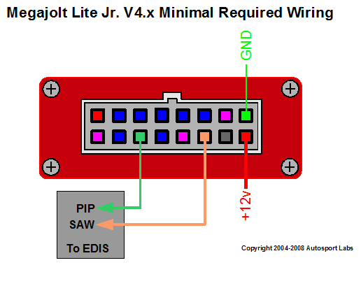
Minimal Wiring for operation
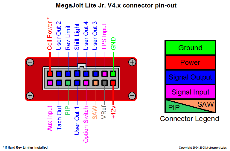
At minimum, the MJLJ needs 4 wires to properly control ignition advance: Power, Ground, and the PIP/SAW signals connecting the EDIS module.
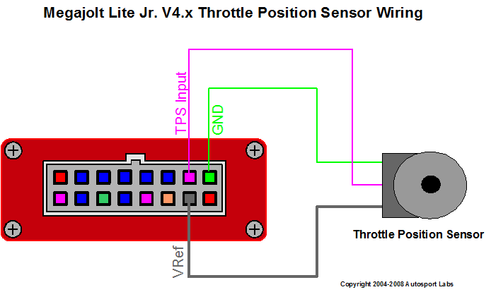
If you are installing a TPS-optioned MJLJ, you will also need to wire the Throttle Position Sensor.
Load Sensing: Manifold Pressure Sensor (MAP) or Throttle Position Sensor (TPS)
MAP Sensor operation
If your MJLJ is optioned with an onboard MAP sensor, find an appropriate spot on your manifold to reference a stable source of vacuum. Run a vacuum line from this location to the barbed connection on the MJLJ.
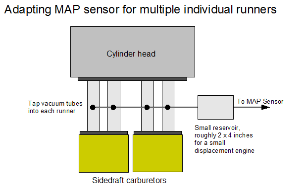
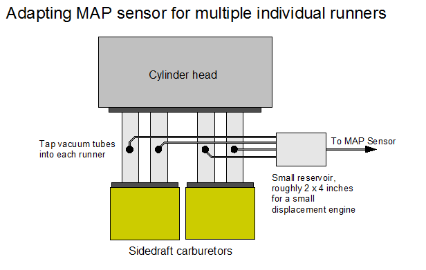
If you have multiple runners and throttle bodies / carburetors, you may need to buy/build a balance tube to average manifold pressure across all runners. Some opt to construct a miniature reservoir to smooth the pulses across all cylinders.
Existing Vacuum Advance vacuum port
Most vacuum advance takeoff ports are designed in such a way that vacuum is measured through a hole, which is actually covered by the edge of the throttle plate at idle. That is called Ported Vacuum. That is done to cut off all vacuum advance at idle, which in turn slows the engine and makes it easier to achieve stable idle with the tiny throttle plate opening used at idle. Vacuum measured on such a port, therefore, has no vacuum at idle, moves to maximum vacuum just off idle, and then decreasing vacuum as the throttle is opened further. The discontinuity just off idle makes such a port awkward to deal with on the load map.
You can test whether you have ported vacuum or not: pull the vac hose off the vacuum advance unit. With your finger over the end of the hose, you should feel vacuum with the engine revved above idle. Assuming yes, let the engine speed drop back to idle. Is there still vacuum? If not (most likely), that means you have ported vacuum, and should find another source of vacuum, somewhere on the manfold.
TPS Sensor operation
For a TPS setup, wire the TPS unit according to the diagram. Be sure to wire the sensor in such a way that the voltage going to the TPS input increases with throttle opening. If you are unsure, do not finalize the connection of these wires until you can verify operation using the PC software. Refer to the Operation Guide for proper Throttle Position Sensor calibration and test.
Interfacing to Tachometers
Using the Tach Out on the MJLJ
Many tachometers can accept the signal emitted from the Tach Out on the MJLJ module. This Tach Out signal provides a 12V pulse for every ignition event. You may use this to provide the signal to compatible tachometers, or to provide a signal to a separate Engine Control Unit, data logger, or other device which requires this signal.
Tachometers that require a high-voltage kickback pulse
Some OEM-style tachometers detect the RPM signal by sensing the high voltage fly back pulse from the ignition coil. In distributor based setups, there is only one ignition coil from which to detect this pulse. With a wasted spark system, this 'signal' is spread across multiple coils. As a result, you will need a way to combine these pulses across multiple coil packs to drive your tachometer.
The following circuit allows the fly back pulse to be detected across individual coil packs while still isolating the coils from each other.
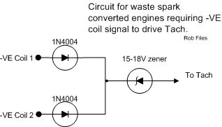
OEM tachometer adapter circuit
If the above circuit does not work, try omitting the Zener diode.
Smiths RVI type tachometers
Note that there are two types of older Smiths tachometers: RVI - current sensing, and RVC - voltage sensing. These letters, and numbers indicating exactly which variant you have, are printed in small white lettering on the bottom of the face of the tachometer. RVI type tachometers work by routing the coil +ve supply wire through an inductive loop of wire inside the tachometer, and are not compatible with the MJLJ. If you have an RVI type tachomoter, you can replace it, have an add-on circuit board added inside (or build one yourself, see http://www.dinoplex.org/tachoconversion for a start), or replace all the inside working parts with those from a newer tachometer ie retain the original face, but change everything else. For that approach you need a donor which has the same angular swing per 1000rpm, as the Smiths gauge.
User Defined Outputs and Shift Light
Usage
The four user-defined outputs provided by the MJLJ can be set to trigger on RPM, Load, or Auxiliary Input thresholds. The separate 'shift light' output triggers only on RPM, but otherwise behaves identically to the user outputs.
The controller firmware applies Hysteresis to the user outputs. For RPM, the hysteresis threshold is 100 RPMs; for Load, the threshold is 1 KPa/1% TPS, and for Auxiliary input, the threshold is 1 configured unit.
The configuration of these outputs is handled bt the Configuration Software- see the Operation Guide for details.
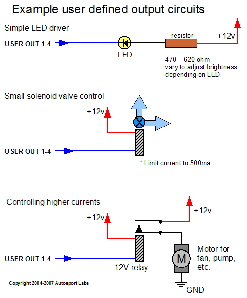
Each output can supply up to 500mA, which is enough to drive LEDs, small incandescent lamps, relays, and small solenoid valves. If you are unsure on the amount of current drawn by the accessory, you can power it manually and measure it's current using a amp meter.
Accessories that have a higher current demand can be controlled by relays, with the MJLJ output driving the relay.
Should you exceed the current capacity of one or more of the user defined outputs and damage the IC that drives the user outputs (ULN2003 darlington array), replace the chip with a new unit- it is socketed for this specific reason.
Wiring
When a User Defined Output is activated the MJLJ connects the pin representing that output to Ground. Therefore, powering a device using the User Defined Outputs involves connecting the positive input of the device to +12V, and the negative input of the device to the appropriate pin representing the MJLJ User Defined Output.
See the following diagram for examples of powering various devices:
Enabling Option Switch
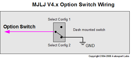
The Option Switch is used to enable on-the-fly switching between Ignition Configurations, controllable via a driver operated switch.
To use this feature, wire a switch according to the following diagram.
See the Operation Guide for more information on using using the dual Ignition Configuration, including how to set the Configuration Software to alert and react to Ignition Configuration switch events.
Rev Limit control
Hard Rev Limit
Since the Ford EDIS module offers no direct rev-limit capability, hard rev limiting is accomplished through a separate circuit which disables power to the ignition coil(s) upon command. The Rev Limit output of the MJLJ is triggered while running when the engine RPM reaches the configured Rev Limit.
We offer a separate Hard Rev Limiter board which can be installed inside the MJLJ enclosure, or mounted externally depending on the user's preference.
Soft Rev Limit
At 100 RPMs before the configured Rev Limit the soft rev limiter is engaged, which significantly reduces engine power by retarding ignition advance to zero. This is confirmed in the Configuration Software where the displayed Ignition Advance goes to zero upon approaching the configured rev limit.
The combination of hard and soft rev limiting should provide effective rev limit protection for most engine configurations. It's worth noting that this system cannot compensate for mechanical over-rev conditions.
Auxiliary Input
The MJLJ offers an auxiliary input which can be used to apply a +/- Ignition Advance correction and/or trigger a user defined output based on the value measured at the input.
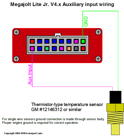
Temperature sensor / variable resistor
By default the MJLJ is optioned to accept an input from a thermistor type temperature sensor, reflecting the most common usage scenario: correcting ignition advance based on engine temperature during warm-up.
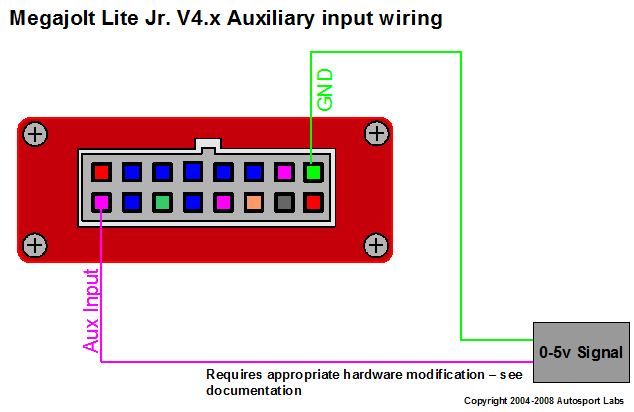
Analog input source
With a small hardware modification, the Auxiliary input can accept a 0-5V signal, useful for reacting to a signal emitted from another device.
Hardware Modification
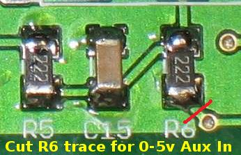
To enable a 0-5v input, disable R6 by performing a slight modification to the circuit board as shown in the following image.
For software configuration of the Auxiliary input, see the Operation Guide.
MJLJ Operation
Verification Steps
Verifying MJLJ operation
After you've double-checked the wiring of the MJLJ, power up the system. The power LED on the MJLJ unit should illuminate.
Connect a timing light and start the engine. You should observe a steady reading with precise changes in ignition advance as RPM and/or load varies. If so, congratulations!! This may be your first time observing the benefits of precision crank-fired ignition!
If the engine does not start, or the advance does not change with RPM, or timing appears jittery or unstable, see the following section for verifying voltages and signals.
Verifying Power
Ensure +12V power is delivered to the MJLJ and EDIS module, enabled only when ignition is 'on' and when cranking. Ensure proper grounding of EDIS module and MJLJ- a central grounding scheme is recommended- Also known as 'Star Grounding'
Verifying Signals
The following table identifies the proper voltages for the various electrical signals used by the system.
| What | Where to measure | Expected Voltage | Symptoms | Cause/Resolution |
|---|---|---|---|---|
| VR Sensor | * Measure across VR Sensor terminal * Measure across EDIS pins 5 and 6 |
* 0 volts when not running; * Approx. 2.5V AC when cranking |
No Spark | EDIS must receive signal from sensor for proper operation. Check gap between sensor and trigger wheel (Max 1 mm); No reading when measuring from sensor may indicate defective sensor; Special Note: Sensor is polarized; reverse connections to sensor if a signal is measured but no spark occurs. |
| PIP Signal | * Measure between EDIS pin 1 and ground * Measure at PIP input on MJLJ and ground |
* Approx. 12V when engine not running; * Approx. 5.5V with engine cranking/running |
No RPM reading on configuration software / No control of Ignition Advance; engine running in "limp home mode" | PIP Signal from EDIS must reach MJLJ in order to measure RPM and command Ignition Advance via SAW pulse. Check wiring between EDIS and MJLJ; ensure appropriate pins are wired. |
| SAW Signal | * Measure between EDIS pin 3 and ground * Measure at SAW output on MJLJ and ground |
* 0V when engine not running; * Less than 0.2V AC when cranking |
RPM Reading in configuration software, but no control of Ignition Advance; engine running in "limp home mode" | SAW Pulse emitted from MJLJ must reach EDIS module in order to command desired Ignition Advance at run-time. Check wiring between MJLJ and EDIS; ensure appropriate pins are wired. |
| TACH output | Measure at TACH_OUT output on MJLJ and ground | * Approx. 5.5V when engine cranking/running | Tachometer does not see TACH_OUT signal; external electronics not reacting to TACH_OUT signal | MJLJ outputs a pulse on TACH_OUT when PIP pulses are received. Ensure MJLJ is powered and properly receiving PIP pulse. |

