GPIO Output: Difference between revisions
(→LEDs) |
(→LEDs) |
||
| Line 9: | Line 9: | ||
====LEDs==== | ====LEDs==== | ||
Most small LED indicator lights can be controlled directly with RCP. Wire constant power (or ignition | Most small LED indicator lights can be controlled directly with RCP. Wire constant power (or ignition/kill switch switched power ) directly to the LED, and wire the ground to the GPIO of the Race Capture Pro. Triggering the GPIO of the RCP will ground the LED turning it on. | ||
====Switches==== | ====Switches==== | ||
Revision as of 17:38, 28 July 2019
GPIO Output to control switches, relays, LEDs, etc
GPIO on the Race Capture Pro devices can be used to control switches, relays, LEDs, and other small devices with a load of 1A or less. If the load is larger than 1A you can use a SPST relay to control it. When in Output mode the GPIO channel will connect to Ground when active and will be open when not active. This means that instead of using the Race Capture Pro to provide power to your switch, relay, or LED, you will use it to provide ground to turn it on instead.
Relays
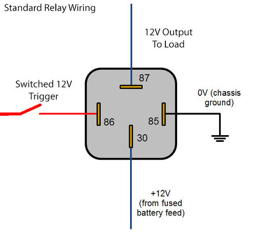
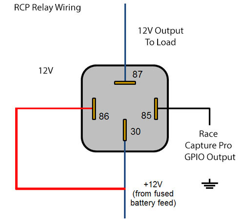
If you have a device you want to control that requires more than 1A, you will need to use a Relay to power it. Normally a SPST relay would have a constant 12v, constant Ground, 12v Output, and input 12v that is used to trigger the relay and sends 12v to the Output. To control a standard 4 pin SPST Relay with Race Capture Pro, You would have constant 12v, but instead of switched 12v input, that will now also always be hot, and instead of constant ground, you will have switched ground controlled by the RCP. When you set the GPIO to active it will ground the relay, triggering it and send 12v power to your desired device.
LEDs
Most small LED indicator lights can be controlled directly with RCP. Wire constant power (or ignition/kill switch switched power ) directly to the LED, and wire the ground to the GPIO of the Race Capture Pro. Triggering the GPIO of the RCP will ground the LED turning it on.
Switches
Video on how to use a 3 way switch with Race Capture Pro GPIO to control diff cooler pump and fans. {{#evu:https://www.youtube.com/watch?v=DDAq7uafYfk}}
I used a 3 way switch to control my diff pump. The switch is an On-Off-On switch. Normally the middle pin would be the constant 12v input and then the other 2 would be the 2 outputs you wanted to control depending on the position of the switch. With the switch in the middle position it is Off (no contact is made). With the switch in the bottom position contact is made with the bottom pin and the middle pin which turns on the device wired to the bottom pin. In the up position, middle pin contact is made with the top pin and 12v is sent to the device wired to the top position. Note: some switches the top pin is connected to the middle pin when the switch is in the down position, and the bottom pin is connected to the middle pin when the switch is on the up position. In our case we need to use ground instead of 12v+. I wanted the up position to make my diff pump always on, and the bottom position the diff pump controlled by RCP. In this case the middle pin was wired to the ground of my relay (see above how to use a relay controlled by ground). The top pin was wired directly to ground, so that in the up position the diff was always on. The bottom pin was wired to my RCP GPIO, such that whenever that GPIO was enabled it would go to ground and trigger the relay, turning on my diff pump.
I also wanted an LED to turn on whenever my diff pump was on so I wired constant 12V+ to the LED, and then a 2nd output wire from the middle pin of my switch to the ground wire of the LED. Whenever the switch grounded my diff pump relay, it would also ground the LED and turn it on.
Lua Scripting for GPIO's
In order to turn on a Race Capture Pro GPIO you need to do so with Lua script. Once turned on(ie. setGpio(1,1) , it will stay on until you explicitly turn it off (ie. setGpio(1,0)
setGpio ( channel, state )
Sets the state of the GPIO channel when the channel is configured for output mode.
- params
- channel: integer 0 - 2
- state: (int / (since 2.10.0) bool) 1 / true = output active; 0 / false = output inactive
- returns:
- none
When the state specified is 1, the output is active (transistor is connected to ground). When state is 0, transistor is disconnected, and pullup resistor is active.
When configured for input mode this function has no effect.
See the Race Capture Pro Lua Scripting GPIO section for more info.


