TireX: Difference between revisions
No edit summary |
|||
| Line 913: | Line 913: | ||
| 0 - 255C | | 0 - 255C | ||
|} | |} | ||
= Hardware configuration Notes = | |||
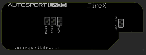
Hardware defaults can be altered by disassembling TireX and adjusting jumpers on the bottom of the circuit board. | |||
* To break a jumper: scrape the space between the jumper pads using a sharp tool, such as a razor blade or very small screwdriver. | |||
* To re-close a jumper: use a fine tip soldering iron and add solder between the jumper pads. | |||
[[image:tirex_jumper_settings.png|500px]] | |||
When re-assembling the board, ensure the sensor and enclosure seals are correctly seated, and torque the enclosure screws evenly. | |||
Revision as of 16:26, 7 April 2022
Introduction
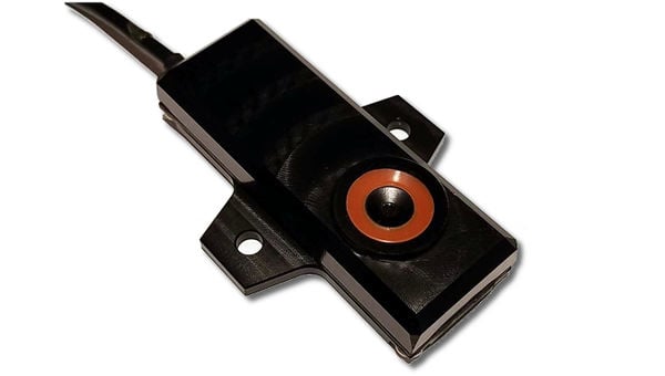
TireX is a powerful and versatile multi-zone tire temperature sensor designed for motorsports applications.
Features
High Performance
TireX can be configured to report up to 16 temperature zones, supporting sample rates up to 64Hz via CAN bus with the powerful embedded 32 bit processor.
Rugged and Compact
TireX features a rugged, low profile design with a wide field of view for space constrained environments.
Flexible Setup
- Temperature zones and sensor calibration is customizable by the end user
- Sensor position can be assigned to provide consistent data reporting between left and right sides of vehicle.
- CAN bus can be set for 1MB or 500K (default is 1MB)
Quick Setup Guide
The following setup assumes you have the following:
- RaceCapture system
- Plug and play wiring harness
- Powered CAN hub kit
- RaceCapture to hub integration cable
Hardware Setup
Provide power to the CAN hub
- Connect the 4 pin pigtail supplied with the CAN hub to a switched +12v source, then plug it into the power connector of the CAN hub. This will provide power to TireX as well as RaceCapture.
Connect RaceCapture system to CAN hub
- Plug the RaceCapture system into the CAN hub using the RaceCapture integration cable.
- Plug the RaceCapture integration cable into the 6 pin connector on the CAN hub.
Connect Each TireX sensor to the Wiring harness
- Connect each TireX sensor to one of the Y-splitter connections of the TireX plug and play harness.
- Connect the last TireX sensor to the end of the harness chain, where the CAN terminator is attached.
Connect the TireX plug and play harness to the CAN2 connection of the CAN hub
- Plug the TireX connection into one of the CAN2 ports on the CAN hub.
Software Setup

Enable CAN bus and set CAN2 to 1MB
Connect the RaceCapture app to your RaceCapture system.
- Go to Setup/CAN bus and ensure the CAN bus is turned ON
- Ensure CAN2 is set to 1M Baud
Enable the TireX CAN mapping
- Go to Setup/CAN mapping
- Ensure CAN Channels are set to ON
- Press the Presets button, then select the TireX 4 zone preset.
- Note - you may need to press the cloud update button to fetch the newest presets.
Write the settings back to your RaceCapture System
- Press the Write button to write your new settings to the system.
Verify the TireX data on the dashboard
Using the overview gauge
- Switch to the RaceCapture dashboard mode.
- Create a new Dashboard screen by pressing the gear icon in the upper right of the screen.
- Select the TireX test dashboard preset
- Note - you may need to press the cloud update button to fetch the newest presets.
Using the raw channels view
- Navigate to the Raw Channels view of the dashboard by pressing the left or right arrows on the dashboard screen.
- You can observe all of the available telemetry channels, including the individual channels for the TireX sensors.
Specifications
Specifications are preliminary and subject to change
| Feature | Description |
|---|---|
| Sensor type | Thermal array |
| Sensor Resolution | 16 x 12 (196 pixels) |
| Object temperature range | 0 - 127.5C (tire temperature mode (factory default)) / 0 - 255C (full frame mode) |
| Field of view | 110 x 75 degrees |
| Accuracy | 1C |
| Temperature zones (tire) | 1 / 2 / 4 (factory default) / 8 / 16 |
| Sample rate | 0.5 - 64Hz (Tire temperature mode, 16Hz factory default) 0.5 - 10Hz (Full frame mode) |
| Processing Engine | 32 bit |
| Configurable positions | 4 (Left-Front (factory default), Right-Front, Left-Rear, Right-Rear); Reversible orientation |
| Emissivity | Configurable (0.95 default) |
| Ambient temperature compensation | Automatic (adjustable offset) |
| Electrical | |
| Interface | CAN 2.0 |
| Supply voltage | 6 - 14v (automotive power) |
| Power | 200mW |
| Harness | M8 4P Male, 250mm length |
| CAN bus | |
| CAN baud rate | 500K and 1M, jumper configurable (1M default) |
| Address space | 4 separate address spaces (configurable via jumper) |
| Termination | No Termination (configurable via jumper) |
| Physical / Environmental | |
| Construction | CNC aluminum |
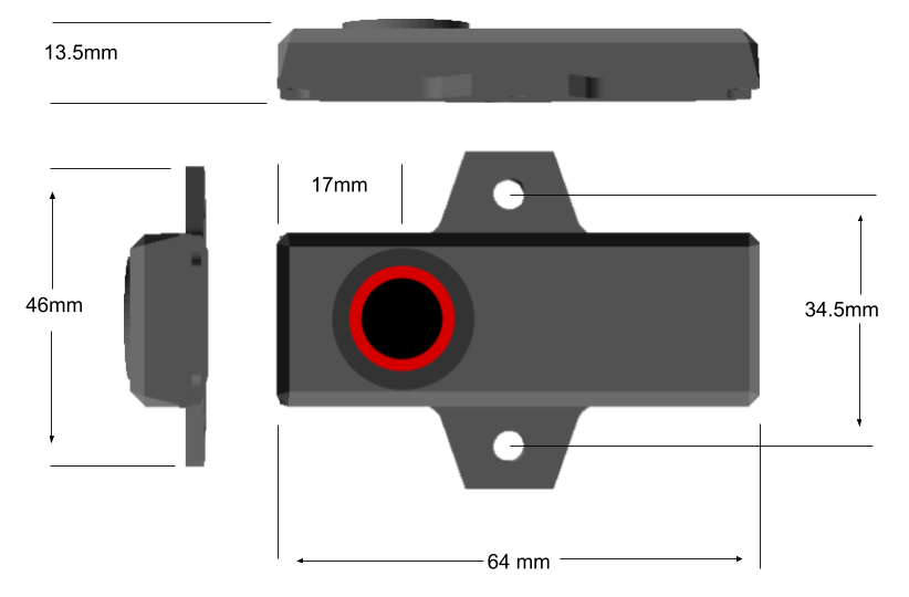
| Dimensions | 64 x 46 x 12.5mm |
| Weight | 10 grams |
| Operating temperature | -40 - 85C |
| IP rating | IP65 |
Dimensions / Mounting
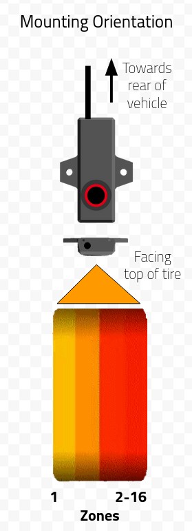
Mounting Orientation
We recommend mounting TireX above the tire, with the cable pointing towards the rear of the vehicle.
- Note: you can clock the mounting point so the sensor is mounted at the front or rear of the wheel well; just ensure the orientation remains the same.
Mounting Distance
TireX has a wide aspect ratio of 110 degrees, so you can use some trigonometry to calculate the distance. Here are some examples:
- 205 width = 71mm
- 225 width = 79mm
- 235 width = 82mm
- 245 width = 85mm
- 255 width = 89mm
- 275 width = 96mm
- 315 width = 110mm
Here's a convenient online calculator
Tip: you can mount TireX at a further distance if you use the middle channels. Example:
- if only using 8 channel, you can mount 2x the distance
- If only using 16 channels, you can mount 4x the distance
- Note: 4 channels is often the resolution of choice to reduce the bulk of data generated, and gives perfectly adequate results for determining tire performance.
Electrical / CAN connection
- Connection is provided by a standard industrial M8 4P male plug. Pigtails and connectors are available from Autosport Labs, or 3rd parties
- TireX is designed to connect to regular automotive 12-14v per our Standard Power interconnect
| Pin | Connecton | Wire Color |
|---|---|---|
| Pin 1 | CAN Low | Brown |
| Pin 2 | Voltage supply (6-14v) | White |
| Pin 3 | CAN High | Blue |
| Pin 4 | Ground | Black |
Zone Configuration
Up to 16 configurable temperature zones
TireX can be configured to report up to 16 temperature zones across the sensor's entire field of vision.
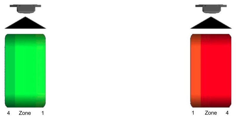
When configured for 2 or more zones, temperature for zones are reported in the order of inside through outside edge.
| Zones | Coverage |
|---|---|
| 1 | Averaged across the entire field of vision |
| 2 | Each zone averaged across 1/2 the field of vision |
| 4 | Each zone averaged across 1/4 the field of vision |
| 8 | Each zone averaged across 1/8 the field of vision |
Reversible orientation based on sensor position
TireX zones are reversed based on the configured sensor position (left vs right side) to allow identical physical sensor mounting orientation between sides.
CAN bus protocol
CAN protocol files
DBC File for standard 4 corner, 4 zone configuration: File:TireX standard.dbc.zip
Overview
The CAN bus API provides the configuration, control and sensor broadcast interface for TireX
Conventions
Formula
- Conversion formulas are expressed as converting the CAN encoded value to real-world value.
- Example:
- Encoded value in CAN message: 95
- Formula: A / 100
- Real-world value: 0.95
Data encoding
Endian
16 and 32 bit values are encoded as little endian.
Single and mulit-byte values
| Value | Symbol Reference |
|---|---|
| 8 Bit values | A |
| 16 bit values | A (low byte) / B (high byte) |
| 32 Bit values | A (low byte) / B / C / D (high byte) |
CAN Baud rate
1M and 500K rates are supported.
1M is enabled by default; cut the jumper labeled BAUD on the bottom of TireX to enable 500K rate.
CAN base ID
A configured TireX sensor will have a CAN base address that is a combination of the Main Base ID + Position Offset based on the installed position of the sensor on the vehicle. This combination creates a final Sensor Base ID.
All broadcast and configuration CAN messages is offset from the final calculated Sensor Base ID.
Default Main Base ID
Default Main CAN base ID is 0xA100 (41216)
Adjusting Main Base ID
The base address is determined by the state of the ADR1 and ADR2 jumpers. By default, the jumpers are closed (bridged); the jumper can be opened by cutting the trace between the pads. To re-close the jumper, add a small amount of solder to bridge the gap between the pads you want to close.
- Note: In the vast majority of the cases you can use the default Main Base ID of 0xA100.
| ADR2 Jumper | ADR1 Jumper | Address |
|---|---|---|
| Closed | Closed | 0xA100 (41216) |
| Closed | Open | 0xB100 (45312) |
| Open | Closed | 0xC100 (49408) |
| Open | Open | 0xD100 (53504) |
- Opening the jumper ADR1 will add (0x1000) 4096 to the base ID
- Opening the jumper ADR2 will add (0x2000) 8192 to the base ID
- Opening both jumpers ADR1 and ADR2 will add (0x3000) 12288 to the base ID.
Sensor Position Offset
The sensor position will offset the Main Base ID by the position of the sensor as defined in the table, to set the final Sensor Base ID.
| Position ID | Sensor Position | Offset |
|---|---|---|
| 0 | Left-Front | 0x0 (0) |
| 1 | Right-Front | 0x100 (256) |
| 2 | Left-Rear | 0x200 (512) |
| 3 | Right-Rear | 0x300 (768) |
Example: default base address (0xA100)
| Sensor Position | Final Sensor Base ID |
|---|---|
| Left-Front | 0xA100 |
| Right-Front | 0xA200 |
| Left-Rear | 0xA300 |
| Right-Rear | 0xA400 |
- Note: Single sensor kits are configured as left-front tire position. This can be changed by sending the appropriate configuration message.
CAN Messages
The announcement message is broadcast by TireX once per second for 10 seconds upon power up.
Announcement
CAN ID: Sensor Base ID + 0
| Offset | What | Data Type | Formula | Value |
|---|---|---|---|---|
| 0 | Sample Rate | unsigned | A * 1 | 0.5 - 64Hz (0 = 0.5Hz) |
| 1 | Temperature Zones | unsigned | A * 1 | Number of configured temperature zones (1 / 2 / 4 / 8 / 16) (factory default is 4) |
| 2 | Sensor Position | Unsigned | A * 1 | Configured sensor position (0=Left-Front / 1=Right-Front / 2=Left-Rear / 3=Right-Rear) |
| 3 | Reserved | |||
| 4 | Reserved | |||
| 5 | Major Version | unsigned | A * 1 | Firmware Major Version Number |
| 6 | Minor Version | unsigned | A * 1 | Firmware Minor Version Number |
| 7 | Patch Version | unsigned | A * 1 | Firmware Patch version number |
Statistics
Broadcast by TireX every 10 seconds.
CAN ID: Sensor Base ID + 2
| Offset | What | Data Type | Formula | Value |
|---|---|---|---|---|
| 0 | Sensor Ambient Temperature | unsigned | A * 1 | 0 - 255C |
| 1 | Reserved | |||
| 2 | Reserved | |||
| 3 | Reserved | |||
| 4 | Reserved | |||
| 5 | Major Version | unsigned | A * 1 | Firmware Major Version Number |
| 6 | Minor Version | unsigned | A * 1 | Firmware Minor Version Number |
| 7 | Patch Version | unsigned | A * 1 | Firmware Patch version number |
Configuration Preferences
This message is broadcasted to TireX to configure the sensor's preferences. The settings are persisted in TireX's flash memory.
CAN ID: Sensor Base ID + 3
- Note: To read the current settings, broadcast a message with this CAN ID with no data (data length of 0) - TireX will reply with the current configuration.
| Offset | What | Data Type | Formula | Value |
|---|---|---|---|---|
| 0 | Sample Rate | unsigned | A * 1 | Rate to report sensor values ( 0.5 - 64Hz) Valid sample rates: 0 (0.5Hz) / 1 (1Hz) / 2 (2Hz) / 4 (4Hz) / 8 (8Hz) / 16 (16Hz) / 32 (32Hz) / 64 (64Hz). Specifying an invalid value will select the default value of 16 |
| 1 | Temperature zones | unsigned | A * 1 | Number of temperature zones. Valid zones: 1 / 2 / 4 / 8 / 16. Specifying an invalid value will select the default value of 4. |
| 2 | Sensor Position | unsigned | A * 1 | Location of the sensor on the vehicle. This position adjusts the Sensor Base ID. Valid Positions 0 (Left-Front) / 1 (Right-Front) / 2 (Left-Rear) / 3 (Right-Rear). Specifying an invalid value will select the default value of 0 (Left-Front). Note: The sensor position affects the orientation of the sensor zones. Sensor Position 1 and 3 will report temperature zones left - right; Position 0 and 2 will report temperature zones right - left. |
| 3 | Frame mode | unsigned | A * 1 | 0 = Standard (Tire Temperature) mode; 1 = Full Frame mode |
| 4 | Reserved | |||
| 5 | Reserved | |||
| 6 | Reserved | |||
| 7 | Reserved |
Calibration Preferences
This message is broadcasted to TireX to configure the sensor's calibration. The settings are persisted in TireX's flash memory.
TireX is calibrated at the factory and normally these values will not need to be changed.
CAN ID: Sensor Base ID + 4
- Note: To read the current settings, broadcast a message with this CAN ID with no data (data length of 0) - TireX will reply with the current configuration.
| Offset | What | Data Type | Formula | Value |
|---|---|---|---|---|
| 0 | Emissivity | unsigned | A / 100 | Emissivity of the target. Default is 0.95 |
| 1 | Ambient temperature compensation | unsigned | A * 1 | Value in C. Default is 2 |
| 2 | Sensor Resolution | unsigned | 16-19 | Sensor ADC resolution, in bits. Default is 18 |
| 3 | Reserved | |||
| 4 | Reserved | |||
| 5 | Reserved | |||
| 6 | Reserved | |||
| 7 | Reserved |
Sensor Temperature Value Broadcast
The following messages will contain the temperature values based on the number of temperature zones configured, broadcast at the currently configured sample rate.
- Note: The sensor position affects the orientation of the sensor zones:
- Position 1 and 3 will report temperature zones left - right;
- Position 0 and 2 will report temperature zones right - left.
1 Zone
CAN ID: Sensor Base ID + 0x20 (32)
| Offset | What | Data Type | Formula | Value |
|---|---|---|---|---|
| 0 | Zone 1 value | unsigned | A / 2 | 0 - 127.5C |
2 Zones
CAN ID: Sensor Base ID + 0x20 (32)
| Offset | What | Data Type | Formula | Value |
|---|---|---|---|---|
| 0 | Zone 1 value | unsigned | A / 2 | 0 - 127.5C |
| 1 | Zone 2 value | unsigned | A / 2 | 0 - 127.5C |
4 Zones
CAN ID: Sensor Base ID + 0x20 (32)
| Offset | What | Data Type | Formula | Value |
|---|---|---|---|---|
| 0 | Zone 1 value | unsigned | A / 2 | 0 - 127.5C |
| 1 | Zone 2 value | unsigned | A / 2 | 0 - 127.5C |
| 2 | Zone 3 value | unsigned | A / 2 | 0 - 127.5C |
| 3 | Zone 4 value | unsigned | A / 2 | 0 - 127.5C |
8 Zones
CAN ID: Sensor Base ID + 0x20 (32)
| Offset | What | Data Type | Formula | Value |
|---|---|---|---|---|
| 0 | Zone 1 value | unsigned | A / 2 | 0 - 127.5C |
| 1 | Zone 2 value | unsigned | A / 2 | 0 - 127.5C |
| 2 | Zone 3 value | unsigned | A / 2 | 0 - 127.5C |
| 3 | Zone 4 value | unsigned | A / 2 | 0 - 127.5C |
| 4 | Zone 5 value | unsigned | A / 2 | 0 - 127.5C |
| 5 | Zone 6 value | unsigned | A / 2 | 0 - 127.5C |
| 6 | Zone 7 value | unsigned | A / 2 | 0 - 127.5C |
| 7 | Zone 8 value | unsigned | A / 2 | 0 - 127.5C |
16 Zones
CAN ID: Sensor Base ID + 0x20 (32)
| Offset | What | Data Type | Formula | Value |
|---|---|---|---|---|
| 0 | Zone 1 value | unsigned | A / 2 | 0 - 127.5C |
| 1 | Zone 2 value | unsigned | A / 2 | 0 - 127.5C |
| 2 | Zone 3 value | unsigned | A / 2 | 0 - 127.5C |
| 3 | Zone 4 value | unsigned | A / 2 | 0 - 127.5C |
| 4 | Zone 5 value | unsigned | A / 2 | 0 - 127.5C |
| 5 | Zone 6 value | unsigned | A / 2 | 0 - 127.5C |
| 6 | Zone 7 value | unsigned | A / 2 | 0 - 127.5C |
| 7 | Zone 8 value | unsigned | A / 2 | 0 - 127.5C |
CAN ID: Sensor Base ID + 0x21 (33)
| Offset | What | Data Type | Formula | Value |
|---|---|---|---|---|
| 0 | Zone 9 value | unsigned | A / 2 | 0 - 127.5C |
| 1 | Zone 10 value | unsigned | A / 2 | 0 - 127.5C |
| 2 | Zone 11 value | unsigned | A / 2 | 0 - 127.5C |
| 3 | Zone 12 value | unsigned | A / 2 | 0 - 127.5C |
| 4 | Zone 13 value | unsigned | A / 2 | 0 - 127.5C |
| 5 | Zone 14 value | unsigned | A / 2 | 0 - 127.5C |
| 6 | Zone 15 value | unsigned | A / 2 | 0 - 127.5C |
| 7 | Zone 16 value | unsigned | A / 2 | 0 - 127.5C |
Full Frame Mode
CAN ID: Sensor Base ID + 0x40 (64)
- Note: Pixels increment linearly by row x column
| Offset | What | Data Type | Formula | Value |
|---|---|---|---|---|
| 0 | Pixel 0 value | unsigned | A | 0 - 255C |
| ... | ... | ... | ... | ... |
| 191 | Pixel 191 value | unsigned | A | 0 - 255C |
Hardware configuration Notes
Hardware defaults can be altered by disassembling TireX and adjusting jumpers on the bottom of the circuit board.
- To break a jumper: scrape the space between the jumper pads using a sharp tool, such as a razor blade or very small screwdriver.
- To re-close a jumper: use a fine tip soldering iron and add solder between the jumper pads.
When re-assembling the board, ensure the sensor and enclosure seals are correctly seated, and torque the enclosure screws evenly.

