Sequential shift light array
Kit assembly
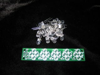
Install Resistors
- R1,R2 Install included 100 ohm resistor (marked 101)
- R3,R4,R5 Install included 270 ohm resistor (marked 271)
Install LEDs
Install LEDs so that the flat side on the LED case matches the outline on the board silkscreen.
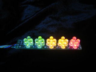
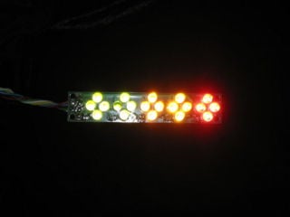
- Cluster A1,A2: Install green LEDs for L1 - L8
- Cluster A3,A4: Install yellow LEDs for L9 - L16
- Cluster A5: Install Red LEDs for L17 - L20
Wiring
Basic Operation
Wire pad +12v to ignition switched +12V.
To activate the following clusters:
- Cluster 1: Connect A1 to ground
- Cluster 2: Connect A2 to ground
- Cluster 3: Connect A3 to ground
- Cluster 4: Connect A4 to ground
- Cluster 5: Connect A5 to ground
Integration with the Megajolt Lite Jr.
User outputs 1-4 + shift light output can be used to control the sequential shift light.
- Cluster 1: Connect A1 to MJLJ User Output 1
- Cluster 2: Connect A2 to MJLJ User Output 2
- Cluster 3: Connect A3 to MJLJ User Output 3
- Cluster 4: Connect A4 to MJLJ User Output 4
- Cluster 5: Connect A5 to MJLJ Shift Light Output
- For MJLJ wiring, see the Installation guide- [[1]] section.
- For software configuration, see the Operation Guide- User output configuration section.


