ESP32-CAN-X2
Introduction
ESP32-CAN-X2 is an innovative, and sophisticated development board that is specifically designed for CAN communication. This development board has all the features of a modern ESP32 development board, integrated Wi-Fi and Bluetooth, along with the extended CAN controller. AutosportsLabs has specifically designed it for advanced CAN communication along with fast processing and computation options. This is a complete how-to-use guide and this user guide will describe each and every step to use the board and harness the maximum potential of the board.
Features
The prominent features of ESP32-CAN-X2 development board are as follows :
- The development board is based on ESP32-SE-WROOM-1-N8R8 microcontroller powerful dual-core Xtensa LX6 CPU running at up to 240 MHz.
- The development board has 384 KB ROM, 512 KB SRAM, 16 KB SRAM in RTC, 8 MB PSRAM
- Two LED’s : LED PWM & LED communication
- Integrated Wi-Fi (802.11b/g/n) and Bluetooth capabilities
- Reset and Boot push button
- USB-C type socket for flashing, and power supply
- Integrated antenna for long range communication
- Additional CAN communication controller CAN using MCP2515
- 6-pin header is strategically positioned at the top for CAN communication
- ESP32-CAN-X2 supports an additional external CAN transceiver
- Easy-to-interface programming. Required no external debugger for flashing
- Integrated CAN transceivers
- Configurable CAN termination resistors, which can be disabled via breakable jumpers
- Flexible power supply options
- Support of a wide choice of commonly used Integrated Development Environments (IDEs)
- Comprehensive free software libraries and examples for CAN communication
Getting started
This section will provide you with comprehensive information about the ESP32-CAN-X2 development board's key components, mechanical layout, and ratings. This detailed information helps you to use the board effectively and efficiently in your projects.
Key Components of ESP32-CAN-X2 Development Board
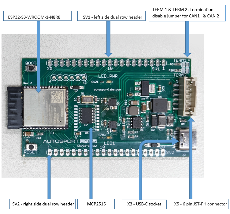
Figure 1 given below indicates the important key components of the ESP32-CAN-X2 Development Board and their location on the board.
Microcontroller
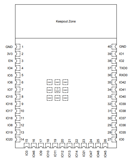
As mentioned above, the ESP32-CAN-X2 Development Board is designed around the ESP32-S3-WROOM-1-N8R8 microcontroller in a 40-pin package. The connections between the development board and the microcontroller are simple and easy to understand. The majority of GPIO pins are directly connected with the external headers, SV1 & SV2, and some pins are reserved internal connections between the board and CAN controllers. The internal connections between the microcontroller and CAN controllers are shown in the CAN controller heading given below. The microcontroller pin layout is shown in Figure 2 given below.
External Connection Header
In addition to the microcontroller, external headers, SV1 & SV2, are the two other important components of this development board. SV1 is the left side dual row header and the SV2 is the right side dual row header. Both of these headers have 20 pins available for connection. These headers provide connections for GPIOs, power output, ground (GND), power input, and CAN communication pins. Both of these header pinouts have standard size, allowing users to connect them using jumper wires, a breadboard, or even solder wires permanently onto the development board. However, while doing the wire connection the customer must make sure that none of them get short circuit. The details regarding the pin's names, numbers, outputs, and functions are given in the Board Pinout section below.
CAN Controllers
Moving on, MCP215, external connected CAN communication controller, and ESP-32 built-in CAN communication controller are two other vital components of this development board. The details of the controller and their connection are as follows.
The MCP2515, operating as the second external CAN controller in this development board, is a specialized component designed for Controller Area Network (CAN) applications. Its features include:
- Implements CAN V2.0B at 1 Mb/s.
- High-Speed SPI Interface (10 MHz)
- Interrupt Output Pin with Selectable Enables
- Multiple receive and transmit buffers
- Low-Power CMOS Technology: - Operates from 2.7V-5.5V, 5 mA active current (typical), 1 μA standby current
The internal CAN controller also works at CAN V2.0. The internal CAN supports two message formats:
- Base frame format (11-bit ID)
- Extended frame format (29-bit ID)
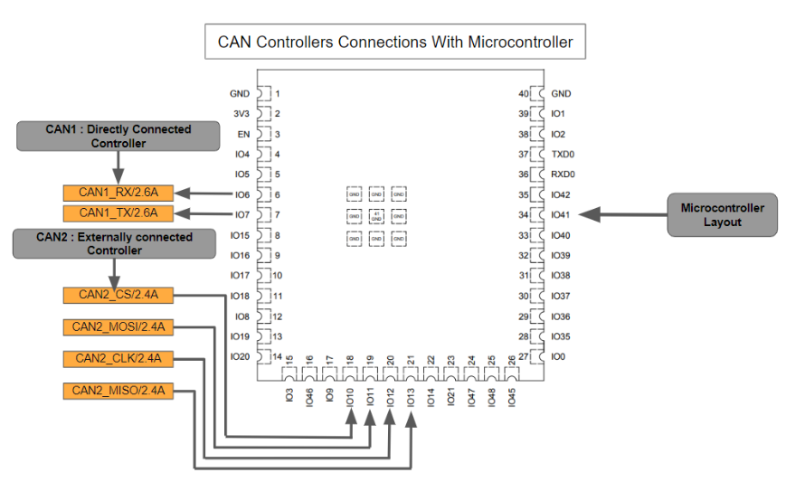
Internal pinout connection between the CAN controllers and ESP32
The internal pinout connection between the CAN controllers and the microcontroller are as following.
- CAN 1 : This is a built-in CAN controller and its RX is connected at IO6 of microcontroller and TX is connected at IO7 of microcontroller. The connections are shown in Figure 3 given below
- CAN 2 : This is the externally connected controller and this controller CS, MOSI, CLK, and MISO are connected at pin number 1O10, 1011, 1012 and 1O13 respectively. The connections are shown in Figure 3 given below
CAN bus information
...brief information about what CAN bus is all about, links to external resources...
Board Pinout
...a visually appealing graphic showing the board pinout...
Flashing firmware
...how to flash the firmware...


