Trigger Wheel Designs
Crank Pulley Strategies
Adapting Trigger Wheel to Existing Crank Pulley
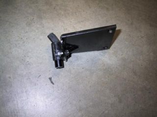
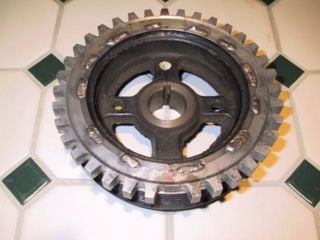
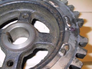
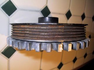
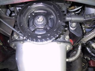
The most common approach is to mate a pre-made Trigger Wheel to the existing OEM crank pulley. Often the trigger wheel must be mounted on the outboard portion of the crank pulley as there is usually not enough room between the crank pulley and block.
Toyota 4AG Trigger wheel installation
Machining Pattern into Crank Pulley
If the crank pulley has extra material to machine the necessary 36-1 pattern, identical results can be obtained compared to the 'traditional' technique of mating special trigger wheels to crank pulleys.
The technique used can be as elaborate as replicating the equivalent trigger wheel teeth pattern into the pulley, to simply milling/drilling a series of holes representing the pattern. Regardless of technique used, it's critical the pattern is accurately machined into the pulley to ensure proper ignition timing.
The following image is an aftermarket VW pulley, modified with the 36-1 pattern using round holes realize the trigger wheel pattern.
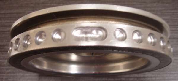
courtesy of Alexander_Monday
The following pulley has it's face modified with the required 36-1 pattern. A clever sensor bracket design will be required for this installation.
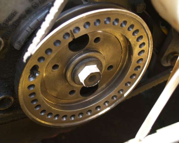
courtesy of pope101
