RacecapturePro MK4 hardware install
Installation
Mounting Orientation
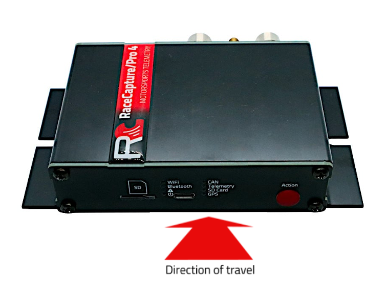
The system can be mounted in various orientations to suit your needs. However, for optimal performance of the accelerometer and gyroscope, it is recommended to mount the system horizontally flat with the indicators facing the driver. After mounting, you can zero out the channels by performing calibration in the Setup section under Accel/Gyro.
Recommended Orientation
Horizontally Flat Indicators facing toward the driver
Alternate Orientations
If needed, the system can also be mounted in alternate orientations. Ensure that any alternate mounting is square to the orientation of the car. Some examples include:
- Upside Down
- Vertical / On Edge
Calibration and Remapping
When an alternate mounting orientation is chosen, it is crucial to remap the accelerometer and gyroscope channels to accurately reflect this change. This can be done in the Setup section under Accel/Gyro.
Mounting Dimensions
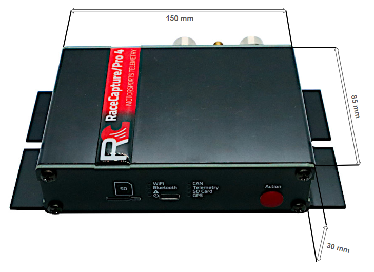
The mounting dimensions of Racecapture Pro Mk4 are given in the image below.
Connections
The RaceCapturePro MK4 has 5 connectors, detailed as follows from left to right:
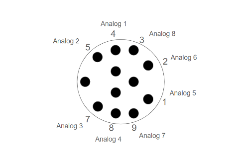
- 12-pin female M12 connector for analog input devices.
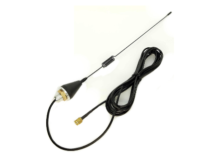
- SMA connector for GPS antenna connection.
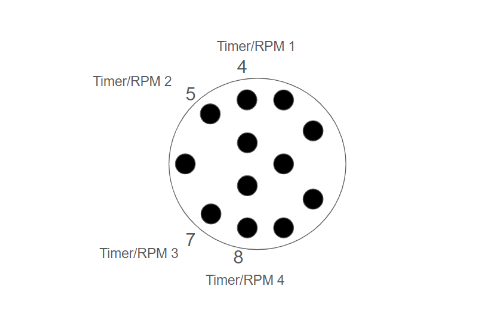
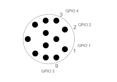
- 12-pin female M12 connector for digital input and RPM sensors.
- 6-pin female M8 connector for CAN1, CAN2, and power connections.
- 4-pin female M8 connector for CAN1 and power connections.
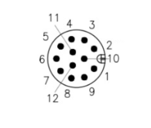
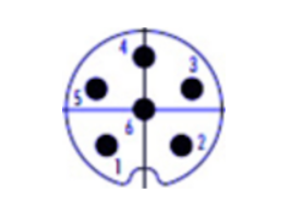
The detailed explanations of connector pinouts are given below.
M12 Analog / Digital Connectors
| Pin | Connection | Analog Mapping | Digital Mapping |
|---|---|---|---|
| 1 | Analog/Digital B1 | Analog 5 | GPIO 1 |
| 2 | Analog/Digital B2 | Analog 6 | GPIO 2 |
| 3 | Analog/Digital B4 | Analog 8 | GPIO 4 |
| 4 | Analog/Digital A1 | Analog 1 | Timer/RPM 1 |
| 5 | Analog/Digital A2 | Analog 2 | Timer/RPM 2 |
| 6 | Vref | 5v @ 0.5A | 5v @ 0.5A |
| 7 | Analog/Digital A3 | Analog 3 | Timer/RPM 3 |
| 8 | Analog/Digital A4 | Analog 4 | Timer/RPM 4 |
| 9 | Analog/Digital B | Analog 7 | GPIO 3 |
| 10 | Ground | ||
| 11 | Ground | ||
| 12 | Ground |
M8 Connectors 4-Pin CAN1+Power
| Pin | Connection | Notes |
|---|---|---|
| 1 | CAN 1 low | |
| 2 | Power | 9-24v / 1A (~12W) |
| 3 | CAN 1 high | |
| 4 | Ground |
M8 Connectors 4-Pin CAN1+Power
| Pin | Connection | Notes |
|---|---|---|
| 1 | CAN 1 low | |
| 2 | CAN 2 low | |
| 3 | CAN 2 high | |
| 4 | Ground | |
| 5 | CAN 1 high | |
| 6 | Power | 9-24v / 1A (~12W) |
OBDII CAN cable
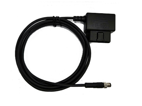
Connecting the Racecapture MK4 to your vehicle's OBDII port is straightforward. The provided M8 connector allows you to easily plug in the OBDII cable using an M8 male to OBDII adapter. This makes for a convenient plug-and-play setup, with no additional connections needed.
SMA Connector
Connect the included GPS antenna to this port. Note: Tighten this connection to 5-6 inches/lbs (just beyond finger tight). Do not over-torque
Antenna Placement Guide
For optimal GPS reception, install a GPS antenna with a clear 360-degree view of the sky, such as on the roof of the vehicle.
Powering
Connect RaceCapture/Pro to a 12V power source, ideally using a switched OBD-II cable.
Power Requirements
| Voltage | 9-24v |
| Current | 1A (~12W) |
Sensor Connectivity
Analog Inputs pins
| Channels | 9 analog input channels, with 8 external and 1 internal for monitoring battery or supply voltage |
| Voltage Range | 0-5V |
| Input Impedance | Greater than 1M ohm |
| Voltage Protection | Up to 400V (intermittent) |
| ADC Precision | 12-bit |
| Maximum Sample Rate | 1000Hz |
| Mapping | Can be configured as Raw, using a linear formula, or an interpolated map |
Note: You can use an analog port to monitor the states of 12V switches, lights, or other 5V-12V On/Off devices. It is recommended to use an inline 10K 1/4 watt resistor to ensure proper functioning and protection of the system. The input should be mapped such that a voltage range of 0-3.0V corresponds to a state of 0, and a voltage range of 3.01V and above corresponds to a state of 1. Even when 12V is applied, the system will display a maximum of approximately 5V, ensuring safe monitoring and accurate state detection of the connected devices.
Guides
- See our comprehensive Sensor Guide for information on connecting various types of analog sensors.
- Also see our guide on Calibrating an Analog Sensor
Frequency / RPM Input
You can connect RPM, wheel speed, and other pulse-type sensors to the RaceCapture/Pro frequency input pins. These inputs are designed to handle various types of frequency-based signals, providing accurate and reliable data for performance monitoring and analysis.
| Input Impedance | Greater than 1M ohm |
| Voltage Protection | Up to 400V (intermittent) |
| ADC Precision | 12-bit |
| Maximum Sample Rate | 1000Hz (logging to SD card) |
| Mapping Supported | The input signals can be mapped to RPM, frequency, or period measurements. |
Signal input quality
To ensure accurate measurements, verify that the source provides a relatively clean pulse signal transitioning between 0 and 5-12 volts. Clean signals are essential for precise and reliable data acquisition.
Special note about RPM inputs
For the best performance and reliability, it is preferred to obtain a clean RPM signal directly from the engine's ECU (Engine Control Unit). This approach minimizes the risk of noise and ensures a more stable signal.
- Verify if the signal you're tapping is driving the ignition coil directly, or if it's feeding into an igniter. If it's powering the coil directly, use the CoilX module to buffer/filter the high-voltage signal.
- If uncertain, visualize the RPM signal using an oscilloscope - you should see a relatively clean square wave as the source.
- If your only source for RPM is the trigger wire driving the ignition coil primary winding, then you will need the CoilX module to buffer/filter the noisy, high-voltage component.
GPIO
RaceCapture/Pro provides 4 General Purpose Input Output (GPIO) ports that can be used to control devices in output mode or read switches and high/low states of electrical signals in input mode.
| Output Mode Type | Open Drain |
| Output Current Capacity | 1A, inductively clamped |
| Input Mode Voltage Range | 0-12V |
| Input Voltage Protection | 0-40V |
| Maximum Sample Rate | 1000Hz |
Input Mode
When configured for input mode, the RaceCapture/Pro sensor input will register a '1' when the input passes a voltage threshold of approximately 3V, and '0' when the input is low (close to 0 volts).
Important Note: When sensing large inductive loads, such as the state of brake lights or the on/off state of a motor, it is recommended to connect a 10K 1/4 watt resistor in line with the GPIO input. This resistor helps protect RaceCapture/Pro from large inductive spikes, ensuring the longevity and reliability of the system.
Output Mode
When configured for output mode, RaceCapture connects that port to the ground and can sink a 1A load per port, which suitable for driving indicators, relays, sending signals to other systems, and driving small devices. Click here for more info
Output Behavior:
- When the port is active, the port will connect to the ground
- When the port is inactive, the port will be an open circuit.
Controlling GPIO Ports
GPIO channels in output mode are controlled by the logic you create with the on-board Lua scripting capability. See the GPIO section of the Lua Scripting reference and collection of Examples.
Communications
RaceCapture/Pro is equipped with multiple CAN bus networks to facilitate communication with various devices. There is a standard convention for selecting which CAN bus to use when connecting devices:
- CAN1: Typically used for connecting Engine Control Units (ECUs), including OBD-II interfaces and after-market ECUs. This CAN bus network is often utilized for critical vehicle data and diagnostics.
- CAN2: Typically used for extended sensor networks, such as AnalogX for analog sensors, TireX for tire pressure monitoring, and other peripheral sensors. These networks provide additional communication channels for expanded data acquisition and monitoring.
CAN Bus Splitter
The M8-6P male connector splits the CAN bus networks into individual CAN1 and CAN2 connections using dual M8-4P female connectors. This splitter allows you to connect devices to the specific CAN buses as needed:
- A Connection: Connects to CAN1
- B Connection: Connects to CAN2
Note: The CAN bus connections provide limited power (1A @ 12V) to devices connected to CAN1 and CAN2. For devices requiring higher power, it is recommended to use the Powered Dual CAN Hub. The Powered Dual CAN Hub provides additional power and helps ensure stable operation for connected devices.
See the CAN bus / ECU integration guide for information on integrating CAN bus communications and CAN channel mapping.
CAN channel specifications
| Can Channel | 2 |
| CAN Baud Rate | 125K, 250K, 500K, 1M Baud |
| CAN Filter | 14 per channel |
| Protocol Support | OBDII PID, custom CAN mapping |
| CAN bus compatibility | CAN 2.0 compatible, 1M baud |
| CAN termination | Software controlled |

