Multiple CAN Systems: Difference between revisions
No edit summary |
mNo edit summary |
||
| (16 intermediate revisions by the same user not shown) | |||
| Line 1: | Line 1: | ||
You can integrate multiple CAN systems into your Race Capture or Podium Connect devices. You may be able to add some of them on the same CAN Channel or you may need to put them on different CAN Channels. Each ASL device has 2 CAN Channels available to connect your CAN systems | - Written by [https://www.facebook.com/scott.barton.76 Scott Barton] of [https://www.facebook.com/ProFormanceCoachingcom ProFormance Coaching] | ||
You can integrate multiple CAN systems into your Race Capture or Podium Connect devices. You may be able to add some of them on the same CAN Channel or you may need to put them on different CAN Channels. Each ASL device has 2 CAN Bus Channels available to connect your CAN systems to. CAN systems that operate at different baud rates CANNOT be on the same CAN Channel. Some systems that operate at the same baud rate may interfere with each other so those might need to be on different CAN channels. | |||
[[Image:AIM_TPMS_OBDII_Data.png|600px]] | [[Image:AIM_TPMS_OBDII_Data.png|600px]] | ||
| Line 19: | Line 21: | ||
==Custom RJ45 Cable== | ==Custom RJ45 Cable== | ||
The [[RaceCapture-Pro_MK2|Race Capture Pro MK2]] or [[RaceCapture-Track_MK2|Race Capture Track]] would require a custom RJ45 cable created. Or there may be a reason you might want to use the RJ45 port on the Race Capture Pro MK3 instead of direct wire. | The [[RaceCapture-Pro_MK2|Race Capture Pro MK2]] or [[RaceCapture-Track_MK2|Race Capture Track]] would require a custom RJ45 cable created. Or there may be a reason you might want to use the RJ45 port on the Race Capture Pro MK3 instead of direct wire. To do this take a short standard ethernet cable (wired in T-568B) and cut one end off. To put the device on CAN 1 you would solder the CAN device's CAN High wire to the Orange wire for Pin2 on the ethernet cable and the CAN device's CAN Low wire to the Pin3 Green/White wire of the ethernet cable. To wire it to CAN 2, use the Blue and Blue/White wires of the ethernet cable for CAN High and CAN Low respectively instead. Do not wire the CAN device's power and ground wires to the ethernet cable, Race Capture will not provide power to your device. Please see this [[RacecapturePro_MK3_hardware_install#RJ45_CAN_.2B_Power_connection|link for more detailed info]]. You can also look at the Custom RJ45 Cross Over Adapter below for more info. | ||
[[Image:RaceCapturePro_MK3_RJ45_pinout.png|link=RacecapturePro_MK3_hardware_install#RJ45_CAN_.2B_Power_connection]] [[Image:TPMS_RJ45_Solder.jpg|500px]] [[Image:TPMS_RJ45.jpg|500px]] | [[Image:RaceCapturePro_MK3_RJ45_pinout.png|link=RacecapturePro_MK3_hardware_install#RJ45_CAN_.2B_Power_connection]] [[Image:TPMS_RJ45_Solder.jpg|500px]] [[Image:TPMS_RJ45.jpg|500px]] | ||
==RJ45 Splitter== | |||
If you already have a CAN system using an RJ45 plug with your Race Capture device, you may need an [https://amzn.to/37NtHLN RJ45 splitter like this $10 one]. | |||
Most of ASL's CAN cables are wired to CAN 1. Note that if the devices are all wired to CAN1 on their RJ45 cables, they will all need to operate at the same baud rate. If they operate at different baud rates or interfere with each other, you would need to use a [[CAN_Crossover_Cable|RJ45 CAN Crossover Cable]] in that case to move that device from CAN1 to CAN2 (see below). | |||
[[Image:RJ45_Splitter.jpg|500px|link=https://amzn.to/37NtHLN]] | |||
==Custom RJ45 CAN Cross Over Adapter== | ==Custom RJ45 CAN Cross Over Adapter== | ||
=====Custom RJ45 CAN Cross Over Adapter to move a device wired to CAN 1 on an RJ45 cable to CAN2 or vice versa.===== | =====Custom RJ45 CAN Cross Over Adapter to move a device wired to CAN 1 on an RJ45 cable to CAN2 or vice versa.===== | ||
If you have a CAN device/system that is already wired to CAN 1 on an RJ45 cable, you may need to move that to CAN 2. This may be because your CAN systems operate at 2 different baud rates or it may be that they interfere with each other, or you may just want to separate the 2 CAN systems. You can do this by creating a custom CAN CrossOver cable that will swap the CAN1 and CAN2 wire pairs. Please see this link for full info on how to do that. | If you have a CAN device/system that is already wired to CAN 1 on an RJ45 cable, you may need to move that to CAN 2 (most of ASL's CAN cables are wired to CAN1). This may be because your CAN systems operate at 2 different baud rates or it may be that they interfere with each other, or you may just want to separate the 2 CAN systems. You can do this by creating a custom [https://wiki.autosportlabs.com/CAN_Crossover_Cable CAN CrossOver cable] that will swap the CAN1 and CAN2 wire pairs. Please see this link for full info on how to do that. | ||
https://wiki.autosportlabs.com/CAN_Crossover_Cable | https://wiki.autosportlabs.com/CAN_Crossover_Cable | ||
[[Image:CANXOverAdapter.jpg|600px]] | [[Image:CANXOverAdapter.jpg|600px|link=CAN_Crossover_Cable]] | ||
==NOTES:== | ==NOTES:== | ||
Most of ASL's CAN cables are wired to CAN1 on the RJ45 plug. | |||
If you wire a device to CAN bus 2 and that device has a Preset, you may have to go into each channel and change it from CAN Bus 1 to CAN Bus 2. | If you wire a device to CAN bus 2 and that device has a Preset, you may have to go into each channel and change it from CAN Bus 1 to CAN Bus 2. | ||
[[Image:RC_CANBus.jpg|500px|link=AIM_Integration_CAN_Mapping#8.29_Click_.2B_Button_to_add_a_New_Channel]] | [[Image:RC_CANBus.jpg|500px|link=AIM_Integration_CAN_Mapping#8.29_Click_.2B_Button_to_add_a_New_Channel]] | ||
Latest revision as of 19:50, 5 January 2021
- Written by Scott Barton of ProFormance Coaching
You can integrate multiple CAN systems into your Race Capture or Podium Connect devices. You may be able to add some of them on the same CAN Channel or you may need to put them on different CAN Channels. Each ASL device has 2 CAN Bus Channels available to connect your CAN systems to. CAN systems that operate at different baud rates CANNOT be on the same CAN Channel. Some systems that operate at the same baud rate may interfere with each other so those might need to be on different CAN channels.
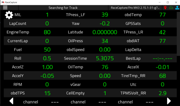
(AIM, CAN TPMS, and OBDII data all on one Race Capture Pro MK3)
Direct Wire
Race Capture Pro MK3
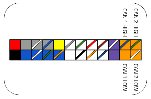
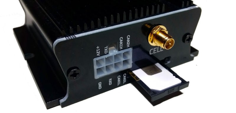
For the Race Capture Pro MK3, you can wire your CAN device to either CAN 1 or CAN 2 on the Molex connector. CAN 1 is recommended as that is what most Presets defaults to if your device has a preset.
Podium Connect
For Podium Connect, you can add wires to CAN2 on the Molex connector using Molex 39-00-0039 pins.
Custom RJ45 Cable
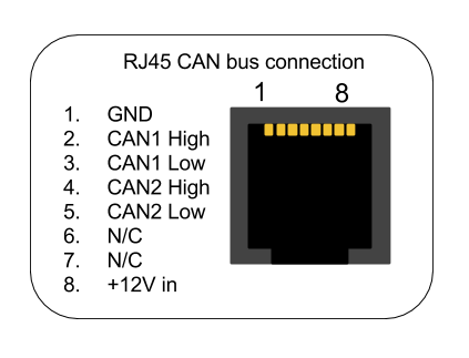
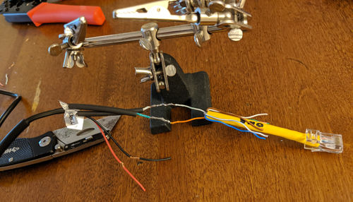
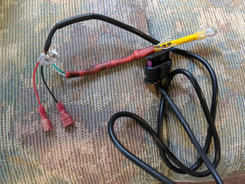
The Race Capture Pro MK2 or Race Capture Track would require a custom RJ45 cable created. Or there may be a reason you might want to use the RJ45 port on the Race Capture Pro MK3 instead of direct wire. To do this take a short standard ethernet cable (wired in T-568B) and cut one end off. To put the device on CAN 1 you would solder the CAN device's CAN High wire to the Orange wire for Pin2 on the ethernet cable and the CAN device's CAN Low wire to the Pin3 Green/White wire of the ethernet cable. To wire it to CAN 2, use the Blue and Blue/White wires of the ethernet cable for CAN High and CAN Low respectively instead. Do not wire the CAN device's power and ground wires to the ethernet cable, Race Capture will not provide power to your device. Please see this link for more detailed info. You can also look at the Custom RJ45 Cross Over Adapter below for more info.
RJ45 Splitter
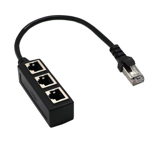
If you already have a CAN system using an RJ45 plug with your Race Capture device, you may need an RJ45 splitter like this $10 one.
Most of ASL's CAN cables are wired to CAN 1. Note that if the devices are all wired to CAN1 on their RJ45 cables, they will all need to operate at the same baud rate. If they operate at different baud rates or interfere with each other, you would need to use a RJ45 CAN Crossover Cable in that case to move that device from CAN1 to CAN2 (see below).
Custom RJ45 CAN Cross Over Adapter
Custom RJ45 CAN Cross Over Adapter to move a device wired to CAN 1 on an RJ45 cable to CAN2 or vice versa.
If you have a CAN device/system that is already wired to CAN 1 on an RJ45 cable, you may need to move that to CAN 2 (most of ASL's CAN cables are wired to CAN1). This may be because your CAN systems operate at 2 different baud rates or it may be that they interfere with each other, or you may just want to separate the 2 CAN systems. You can do this by creating a custom CAN CrossOver cable that will swap the CAN1 and CAN2 wire pairs. Please see this link for full info on how to do that. https://wiki.autosportlabs.com/CAN_Crossover_Cable
NOTES:
Most of ASL's CAN cables are wired to CAN1 on the RJ45 plug.
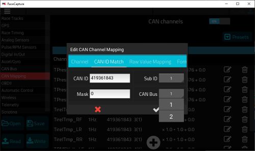
If you wire a device to CAN bus 2 and that device has a Preset, you may have to go into each channel and change it from CAN Bus 1 to CAN Bus 2.

