RacecapturePro MK3 hardware install: Difference between revisions
(→GPIO) |
No edit summary |
||
| (4 intermediate revisions by 2 users not shown) | |||
| Line 7: | Line 7: | ||
* Mount as flat as possible for best performance from the built-in accelerometer / gyro. | * Mount as flat as possible for best performance from the built-in accelerometer / gyro. | ||
* Once mounted, you can zero out the channels by performing the calibration in Setup / Accel/Gyro. | |||
===Alternative Mounting=== | ===Alternative Mounting=== | ||
| Line 238: | Line 239: | ||
| Raw voltage / linear formula / interpolated map | | Raw voltage / linear formula / interpolated map | ||
|} | |} | ||
Note: You can use an analog port to monitor the states of 12v switches, lights, or other 5v-12v On/Off devices. It is recommended that you use a 10K 1/4 watt resistor inline. Map the input to 0-3.0v = 0; and 3.01V+ = 1. Even if 12v is applied, ~5V will be the max displayed. | |||
===Connecting Sensors=== | ===Connecting Sensors=== | ||
Connect each analog sensor to the respective analog sensor input on the main connector. | Connect each analog sensor to the respective analog sensor input on the main connector. | ||
| Line 244: | Line 248: | ||
===Guides=== | ===Guides=== | ||
* See our comprehensive [[RaceCapturePro_Sensors Sensor Guide]] for information on connecting various types of analog sensors. | * See our comprehensive [[RaceCapturePro_Sensors|Sensor Guide]] for information on connecting various types of analog sensors. | ||
* Also see our guide on [[RaceCapturePro_Calibrate_Sensor|Calibrating an Analog Sensor]] | * Also see our guide on [[RaceCapturePro_Calibrate_Sensor|Calibrating an Analog Sensor]] | ||
| Line 311: | Line 315: | ||
===[[GPIO_Output|Output Mode]]=== | ===[[GPIO_Output|Output Mode]]=== | ||
When configured for output mode, RaceCapture can sink a 1A load per port, suitable for driving indicators, relays, sending signals to other systems and driving small devices. | When configured for output mode, RaceCapture connects that port to ground and can sink a 1A load per port, suitable for driving indicators, relays, sending signals to other systems and driving small devices. [[GPIO_Output|Click here for more info.]] | ||
====Output Behaviour==== | ====Output Behaviour==== | ||
Latest revision as of 21:32, 19 July 2021
Installation
Mounting Orientation
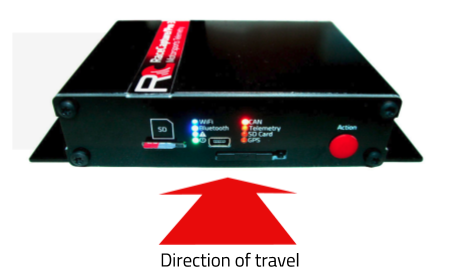
The default and recommended mounting orientation is flat with indicators facing aft for driver visibility (if mounted forward of the driver).
- Mount as flat as possible for best performance from the built-in accelerometer / gyro.
- Once mounted, you can zero out the channels by performing the calibration in Setup / Accel/Gyro.
Alternative Mounting
You can mount the system in other orientations. For best accelerometer and gyro performance, it's recommended you mount in an orientation that's square to the orientation of the car.
- Example:
- Upside down
- Vertical / on edge
If an alternate mounting orientation is chosen, you should re-map the accelerometer and gyro channels to reflect this change.
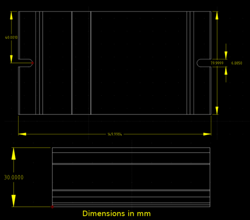
Mounting Dimensions
(Click to zoom)
Connections
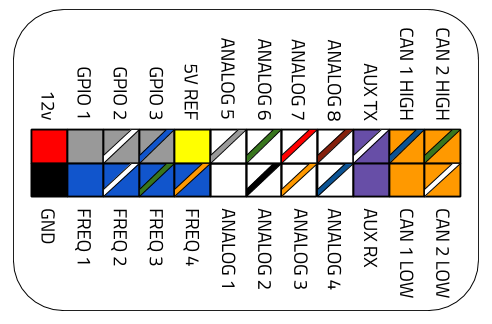
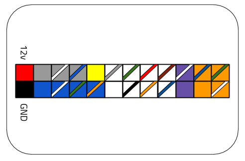
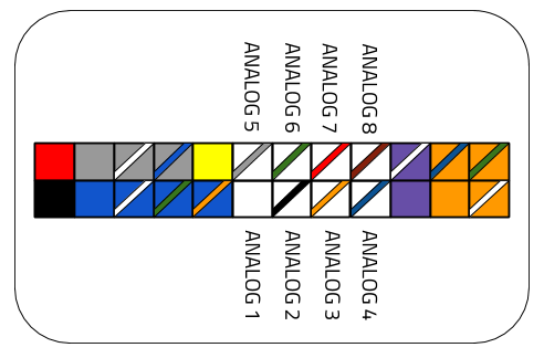
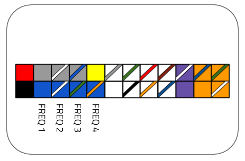
Main Connector
The main connector provides access to all power, sensor and communications for the RaceCapture/Pro system.
| Power | |
|---|---|
| Connection | Color |
| 12v | Red |
| Ground | Black |
| Frequency / RPM sensor inputs | |
| Blue | Frequency / RPM input 1 |
| Blue / White stripe | Frequency / RPM input 2 |
| Blue / Green Stripe | Frequency / RPM input 3 |
| Blue / Orange Stripe | Frequency / RPM input 4 |
| Voltage Reference | |
| Yellow | +5v reference |
| Analog Sensor Inputs | |
| White | Analog Input 1 |
| White / Black Stripe | Analog Input 2 |
| White / Orange Stripe | Analog Input 3 |
| White / Blue Stripe | Analog Input 4 |
| White / Gray Stripe | Analog Input 5 |
| White / Green Stripe | Analog Input 6 |
| White / Red Stripe | Analog Input 7 |
| White / Brown Stripe | Analog Input 8 |
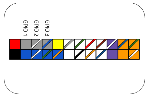
| General Purpose Input / Output (GPIO) | |
| Gray | GPIO 1 |
| Gray / White Stripe | GPIO 2 |
| Gray / Blue Stripe | GPIO 3 |
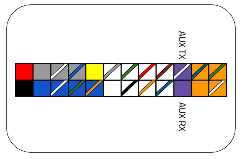
| Auxiliary Serial Input | |
| Purple / White Stripe | Auxiliary RS232 Serial TX |
| Purple | Auxiliary RS232 Serial RX |
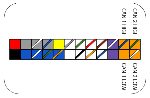
| CAN Bus | |
| Orange / Blue Stripe | CAN 1 High |
| Orange | CAN 1 Low |
| Orange / Green Stripe | CAN 2 High |
| Orange / White Stripe | CAN 1 Low |
Plug Connector Type
The connector is a standard 24 pin Molex Mini Fit Jr.
- Plug Housing: Molex Mini Fit Jr. 39012240
- Compatible Pins: Molex 39000039
Other connector sources
A 24 pin Molex harness from a computer power supply can also work as a secondary wiring harness.
GPS
Connect the included GPS antenna to this port.
- Note: Tighten this connection to 5-6 inch/lbs (just beyond finger tight). Do not over torque
Cellular Telemetry
If optioned with the 3.5G real-time cellular telemetry module, connect the cellular antenna to this port.
- Note: Tighten this connection to 5-6 inch/lbs (just beyond finger tight). Do not over torque
Antenna Placement Guide
GPS
For optimal GPS reception, install GPS antenna with a clear 360 degree view of the sky, such as on the roof of the vehicle.
Cellular antenna
For optimal cellular performance, install the cellular antenna on the roof of the vehicle, using the roof as a ground plane.
Antenna separation
It's recommended you separate the GPS and cellular antennas as reasonably far apart as possible, such as mounting at opposite ends of the roof.

- Note: - about 3 foot / 1 meter separation is ideal.
RJ45 CAN + Power connection
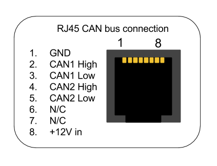
The RJ45 port provides connections for power and both CAN channels.
(Orientation is looking into the RJ45 port)
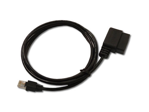
OBDII CAN cable
The RJ45 port is normally provided for the OBDII CAN cable accessory for a convenient plug and play OBDII connection
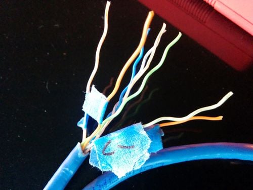
Custom Cable
You can also use a common RJ45 ethernet cable to provide power, ground and CAN bus data for a custom application.
| Connection | CAT5 EIA-T568B RJ45 cable |
|---|---|
| +12v | Brown |
| Ground | Orange/White |
| CAN 1 High | Orange |
| CAN 1 Low | Green/White |
| CAN 2 High | Blue |
| CAN 2 Low | Blue/White |
Note: These color codes assume EIA-T568B RJ45 cable (check printing on the cable to confirm)
Powering
Connect RaceCapture/Pro to a 12v source, ideally switched with main power or via ignition power.
Power requirements
| Voltage | 12-24v |
| Fused circuit | 5A max |
Powering Notes
- You can also power via the RJ45 connector, useful when plugging in to OBDII.
- Power can not be passed between RJ45 and the main connector, to prevent backfeeding of circuits in the vehicle.
Sensors
Analog Sensor inputs
9 analog sensor input channels are provided: 8 are available for dedicated sensors, plus a 9th internal channel assigned to battery voltage.
| Voltage Range | 0-5v |
| Input Impedance | Greater than 1M ohm |
| Voltage protection | 400v (intermittent) |
| ADC precision | 12 bit SAR |
| Maximum Sample Rate | 1000Hz (logging to SD card) |
| Mapping supported | Raw voltage / linear formula / interpolated map |
Note: You can use an analog port to monitor the states of 12v switches, lights, or other 5v-12v On/Off devices. It is recommended that you use a 10K 1/4 watt resistor inline. Map the input to 0-3.0v = 0; and 3.01V+ = 1. Even if 12v is applied, ~5V will be the max displayed.
Connecting Sensors
Connect each analog sensor to the respective analog sensor input on the main connector.
Guides
- See our comprehensive Sensor Guide for information on connecting various types of analog sensors.
- Also see our guide on Calibrating an Analog Sensor
Frequency / RPM sensor input
You can connect RPM, wheel speed and other pulse-type sensors to RaceCapture/Pro frequency input pins.
| Voltage Range | 0-12v |
| Input Impedance | Greater than 1M ohm |
| Voltage protection | 400v (intermittent) |
| Maximum Sample Rate | 1000Hz (logging to SD card) |
| Mapping supported | RPM / Frequency / Period |
Signal input quality
Verify the source provides a relatively clean, pulse signal that transitions between 0 and 5-12 volts.
Special note about RPM inputs
For best performance and reliability, it's preferred to obtain a clean RPM signal from the engine's ECU.
- Verify if the signal you're tapping is driving the ignition coil directly, or if it's feeding into an igniter. If it's powering the coil directly, use the CoilX module to buffer / filter the high voltage signal.
- If uncertain, visualize the RPM signal using an oscilloscope - you should see a relatively clean square wave as the source.
- If your only source for RPM is the trigger wire driving the ignition coil primary winding, then you will need the CoilX module to buffer / filter the noisy, high-voltage component.
Connecting Sensors
Connect each sensor connection to the respective frequency sensor input on the main connector.
See our RPM connection guide for more information connecting and calibrating these frequency / RPM channels.
GPIO
RaceCapture/Pro provides 3 General Purpose Input Output (GPIO) ports which you can use to control devices (Output mode) or read switches or high / low states of electrical signals.
Specifications
| Output mode type | Open Drain (connects ground when activated) |
| Output current capacity | 1A, inductively clamped |
| Input mode voltage range | 0-12v |
| Input voltage protection | 0-40v - inductive protection up to 1A |
Input Mode
When configured for input mode, the RaceCapture/Pro sensor input will register a '1' when the input passes a voltage threshold of approximately 3v, and '0' when the input is low (close to 0 volts).
Important Note: when sensing large inductive loads, such as sensing brake light state or sensing the on/off state of a motor, connect a 10K 1/4 watt resistor in-line with the GPIO input to protect RaceCapture/Pro from a large inductive spike.
Output Mode
When configured for output mode, RaceCapture connects that port to ground and can sink a 1A load per port, suitable for driving indicators, relays, sending signals to other systems and driving small devices. Click here for more info.
Output Behaviour
- When the port is active, the port will connect to ground.
- When the port is inactive, the port will be an open circuit.
GPIO Connections
Controlling GPIO Ports
GPIO channels in output mode are controlled by the logic you create with the on-board Lua scripting capability.
- See the GPIO section of the Lua Scripting reference and collection of Examples.
Communications
CAN Channels 1 / 2
Two CAN channels are provided on the main connector as well as on the RJ45 connector.
See the CAN bus / ECU integration guide for information on integrating CAN bus communications and CAN channel mapping
| CAN channels | 2 |
| CAN Baud Rate | 125K, 250K, 500K, 1M Baud |
| CAN Filters | 14 per channel |
| CAN bus compatibility | CAN 2.0 compatible, 1M baud |
| CAN termination | Software controlled |
Connections
Auxiliary Serial
One Auxiliary RS232 compatible serial port is available on the main connector. You can use this to communicate with external devices that uses standard RS232 signaling for communications.
Control and communication of this Auxiliary serial port is provided through Lua Scripting, where you can control and receive data from external systems and map received data to virtual channels that can be provided in the telemetry stream.
- See the Lua scripting guide and Examples

