CAN Bus Integration: Difference between revisions
(added main content and script framework) |
|||
| (56 intermediate revisions by 2 users not shown) | |||
| Line 1: | Line 1: | ||
=Introduction= | =Introduction= | ||
Mapping an existing CAN bus system can be easy if documentation is available. ECU manufacturers are | Mapping an existing CAN bus system can be easy with basic knowledge of CAN mapping, and most importantly - if CAN technical documentation is available for the device in question. Fortunately, ECU and sensor manufacturers are keen on providing documentation as they naturally want their devices as inter-operable as possible. | ||
If documentation isn't available, the problem is just more interesting | If documentation isn't available, the problem is just more interesting to someone with the time and skills, and it helps that the CAN bus system is open in terms of it's messaging format and provides simple 8 byte message packets with a numeric identifier, much like an internet IP address. | ||
=Prerequisites= | |||
To successfully perform a custom CAN integration, it's helpful to have the following knowledge before you get started. | |||
* Basic knowledge of wiring and making wiring connections | |||
* Basic knowledge of CAN bus technology. [https://www.google.com/webhp?&ion=1#q=can+bus+tutorial Here are some some helpful links.] | |||
Also, if you need to make a custom mapping because no preset exists for your device: | |||
* Basic understanding of math | |||
* Basic understanding of data represented as [https://computer.howstuffworks.com/bytes.htm bits and bytes] | |||
If this appears challenging, get a friend to help and / or [http://forum.autosportlabs.com jump onto the forums] and ask for assistance - another forum member might have mapped the same system as you're working with, or can help you with your particular project. | |||
=Preset configurations= | |||
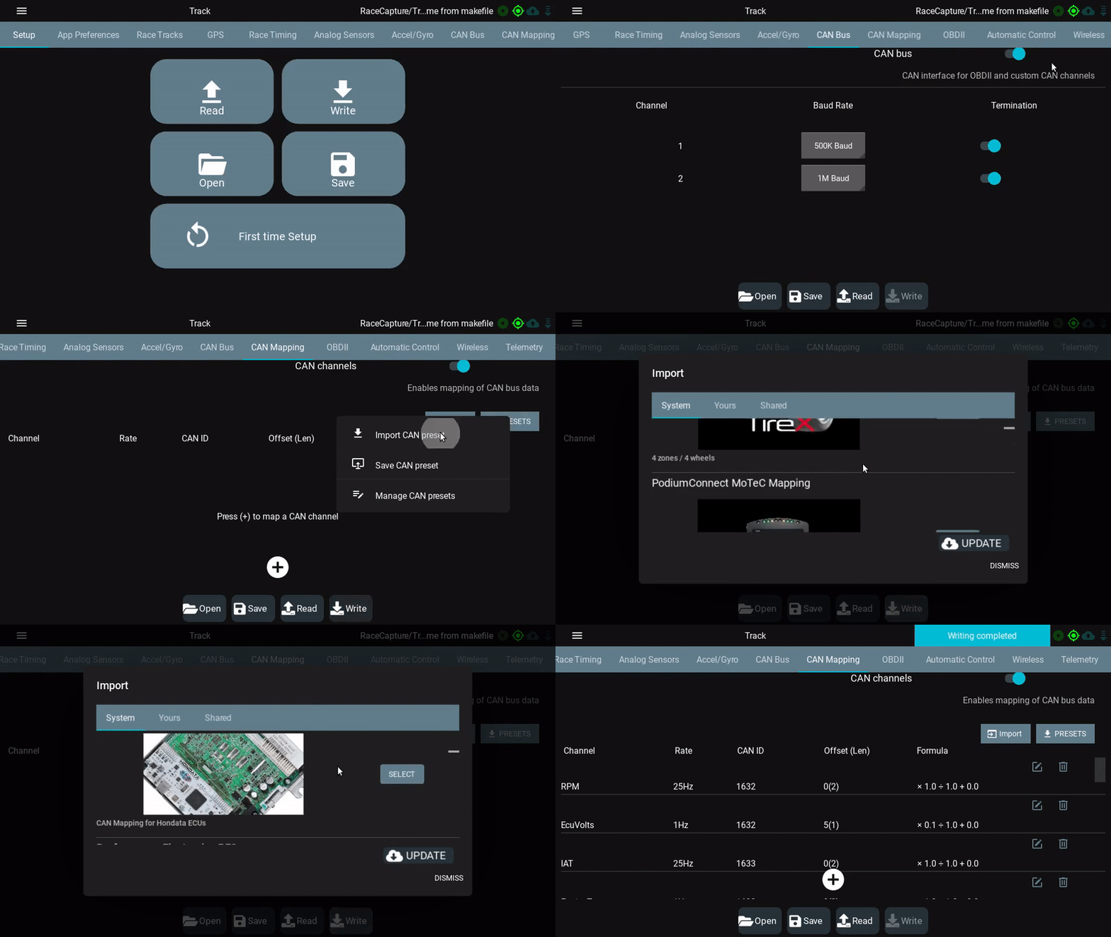
Fortunately, we have a [[RCP_CAN|growing library of pre-set configurations for different ECUs and sensors]]. As time goes on, the chances grow that you'll be able to simply click a button and have a quickly working CAN integration. | |||
[[image:racecapture_select_can_preset.gif]] | |||
==Wiring CAN bus== | |||
Integrating a CAN-enabled device to RaceCapture involves connecting the CAN bus connections to RaceCapture. | |||
Each CAN device has two wires that provides data: | |||
* CAN high (CANH) | |||
* CAN low (CANL) | |||
When you connect the device to the CAN bus, you would connect the CAN high and CAN low wires of the device to the CAN high and CAN low wires of RaceCapture. | |||
===Choosing the CAN bus to connect=== | |||
RaceCapture has multiple CAN bus networks. There is a convention for choosing which CAN bus when connecting a device: | |||
* CAN1 - typically used for ECUs (OBDII and after-market) | |||
* CAN2 and higher - typically used for extended sensor networks, such as AnalogX, TireX, etc. | |||
[[File:CAN Connection 1.png|700px]] | |||
This approach isolates the extended sensors from the car's ECU, especially important when working with OEM ECU networks. | |||
* '''Note''' - this is not a hard and fast rule, but a convention. Advanced users may choose any configuration that meets their needs. | |||
===Plug and Play connector system=== | |||
* Applies to | |||
** RaceCapture/Track MK3 | |||
** RaceCapture/Pro MK4 | |||
** PodiumConnect MK2 | |||
[[Harness_specifications|See the full plug and play harness specification]] | |||
====Power + CAN Single interconnect==== | |||
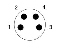
* Connector: M8 4P, A coding | |||
[[file:M8_4P_male_pinout.jpg|200px]] | |||
''Male connector pictured'' | |||
{| class="wikitable" | |||
|- | |||
! Pin !! Connection !! Notes | |||
|- | |||
| 1 || CAN low || White | |||
|- | |||
| 2 || Power || Red, 9-24v / 1A (~12W) | |||
|- | |||
| 3 || CAN high || Green | |||
|- | |||
| 4 || Ground || Black | |||
|} | |||
==Dual CAN + power interconnect== | |||
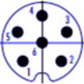
* Connector: M8 6P, A coding | |||
[[file:M8_6P_male_connector.png]] | |||
''Male connector pictured'' | |||
{| class="wikitable" | |||
|- | |||
! Pin !! Connection !! Notes | |||
|- | |||
| 1 || CAN1 low || | |||
|- | |||
| 2 || CAN2 low || | |||
|- | |||
| 3 || CAN2 high || | |||
|- | |||
| 4 || Ground || | |||
|- | |||
| 5 || CAN1 high || | |||
|- | |||
| 6 || Power || 9-24v / 1A (~12W) | |||
|} | |||
===Molex connector=== | |||
* Applies to | |||
** RaceCapture/Pro MK3 | |||
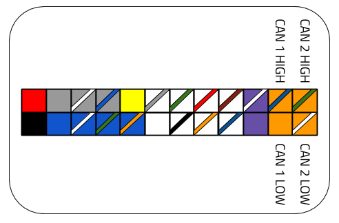
Both CAN ports are available on the molex connector: | |||
[[file:RaceCapture_Pro_MK3_Molex_CAN_pinout.png]] | |||
===RJ45 connector=== | |||
* Applies to | |||
** RaceCapture/Pro MK3 | |||
** RaceCapture/Pro MK2 | |||
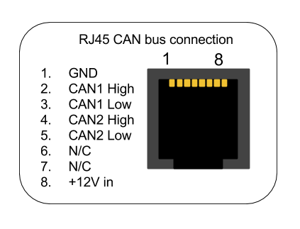
This port is typically used for the optional CAN-OBDII interface cable, but can also be used for custom integrations. Both CAN channels are available on the RJ45 connection. | |||
====Cabling==== | |||
You can custom crimp an RJ45 cable, or you can use a standard CAT-5 ethernet cable with RJ45 connectors to integrate with RaceCapture/Pro. | |||
{| class="wikitable" style="text-align:center; width:700px; height:200px;" | |||
|+ RJ45 Power, ground and CAN bus connections to RaceCapture/Pro | |||
|+ EIA-T568B RJ45 cable color codes (check printing on the cable to confirm) | |||
|- | |||
! Connection | |||
! RaceCapture/Pro (RJ45 cable) | |||
|- | |||
| +12v | |||
| Brown | |||
|- | |||
| Ground | |||
| Orange/White | |||
|- | |||
| CAN 1 High | |||
| Orange | |||
|- | |||
| CAN 1 Low | |||
| Green/White | |||
|- | |||
| CAN 2 High | |||
| Blue | |||
|- | |||
| CAN 2 Low | |||
| Blue/White | |||
|} | |||
[[File:RaceCapturePro_MK3_RJ45_pinout.png]] | |||
* '''Important note for MK2:''' The +12v connection on the RJ45 is connected internally to the +12v on the terminal block on RaceCapture/Pro MK2. It's recommended you only power via one source - RJ45 or terminal block - if you have both connected at the same time, you may cause back-feeding of power through RaceCapture/Pro, which may cause damage to the unit. '''Note: RaceCapture/Pro MK3 has internal protection diodes which avoids this issue.''' | |||
==Researching CAN Bus protocol== | ==Researching CAN Bus protocol== | ||
If you are working to integrate an ECU, first ask the manufacturer for their CAN bus specification. This documentation will provide a breakdown of channels - such as RPM, temperatures and pressures and describe how they appear in the CAN message stream. A good example is the [http://www.msextra.com/doc/pdf/Megasquirt_CAN_Broadcast.pdf Megasquirt CAN Broadcast Specification] | If you are working to integrate an ECU, first ask the manufacturer for their CAN bus specification. This documentation will provide a breakdown of channels - such as RPM, temperatures and pressures and describe how they appear in the CAN message stream. A good example is the [http://www.msextra.com/doc/pdf/Megasquirt_CAN_Broadcast.pdf Megasquirt CAN Broadcast Specification]. | ||
===CAN Bus documentation=== | ===CAN Bus documentation=== | ||
The manufacturer provided document will show for each channel the following information: | |||
* '''Channel''': (RPM, Engine Temperature, Throttle Position, etc) | * '''Channel''': (RPM, Engine Temperature, Throttle Position, etc) | ||
* '''CAN Identifier''': The CAN Identifier for each channel. This may appear in either 11 or the extended 29 bit format. Typically 11 bits are used. | * '''CAN Identifier''': The CAN Identifier for each channel. This may appear in either 11 or the extended 29 bit format. Typically 11 bits are used. | ||
* '''Offset''': where the data starts within the 8 byte CAN message. An offset of 0 means the data starts on the first byte. | * '''Offset''': where the data starts within the 8 byte CAN message. An offset of 0 means the data starts on the first byte. | ||
* '''Length''': Typically 1 or two bytes | * '''Length''': Typically 1 or two bytes | ||
* '''Scaling''': The raw value from the message is often scaled to a real world value. Typically this is provided as a multiplier and adder value. | * '''Scaling''': The raw value from the message is often scaled to a real world value. Typically this is provided as a multiplier and adder value, but may also specify a divider. | ||
=== | ===Big Endian or Little Endian mode=== | ||
Additionally, the manufacturer will specify if multi-byte (16, 24 or 32 bit) values are presented in MSB (Most Significant | Additionally, the manufacturer will specify if multi-byte (16, 24 or 32 bit) values are presented in '''Big Endian''' (MSB (Most Significant Bit)) or '''Little Endian''' (LSB (Least Significant Bit)) mode. | ||
BigEndian mode data will have the high byte presented first in the data packet and is typically the most common format. | |||
Example: | Big Endian / Little Endian Example: | ||
* Decimal value: 1000 | * Decimal value: 1000 | ||
* Hex Value in | * Hex Value in Big Endian: 0x03E8 | ||
* Hex Value in | * Hex Value in Little Endian: 0xE803 | ||
If provided in a CAN message, it might show up as follows in this hypothetical message: | If provided in a CAN message, it might show up as follows in this hypothetical message: | ||
| Line 41: | Line 177: | ||
(Decimal) [xx] [232] [3] [xx] [xx] [xx] [xx] [xx] | (Decimal) [xx] [232] [3] [xx] [xx] [xx] [xx] [xx] | ||
=Enabling CAN bus= | |||
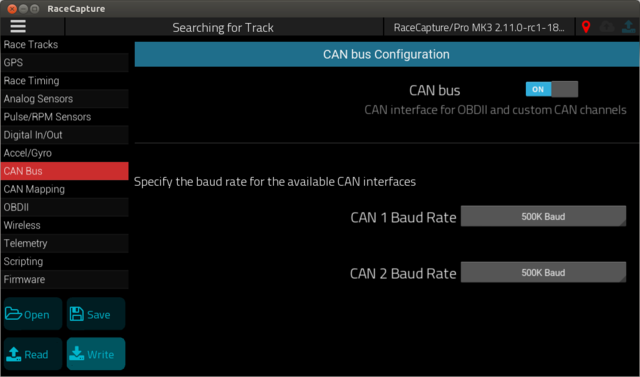
Once you have the CAN connections wired, you can enable CAN bus on your RaceCapture system. This provides the ability to turn on the CAN bus connectivity at the global level, and allows you to set the baud rate for the individual CAN bus channels. | |||
[[file:RaceCapture_CAN_bus_settings.png|640px]] | |||
After making changes, be sure to '''write''' your configuration back to your RaceCapture device. | |||
=Mapping CAN data to channels= | |||
==Direct CAN mapping== | |||
The direct CAN mapping capabilities will allow easy mapping of 99% of existing CAN based ECUs and sensors. For the outliers, you can map CAN data using the [[CAN_Bus_Integration#Lua_scripting|on-board Lua Scripting]], allowing for any custom formula or logic. | |||
===Adding a channel=== | |||
* To start, connect to your RaceCapture device and ensure the current configuration is read, or open a previously saved configuration. | |||
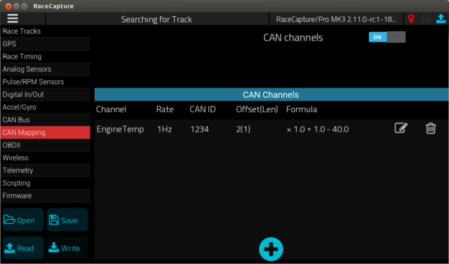
* Navigate to the CAN Mapping page. | |||
* Ensure '''CAN channels''' is set to '''on''' | |||
* Press the (+) button to add your first channel. | |||
[[file:RaceCapture_CAN_mapping.png|640px]] | |||
====Defining the Channel==== | |||
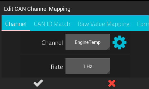
The first tab will let you define the channel name and sample rate. | |||
[[file:RaceCapture_CAN_mapping_channel_tab.png]] | |||
* '''Channel Name''': selecting a channel name from the drop-down will pre-set the units, min, max and precision to typical values. | |||
You can customize this by pressing the gear icon to customize: | |||
** '''Channel Name''' - Specify the channel name. We recommend formatting the name with CamelCase with a leading capital letter, and no spaces or underscores. | |||
** '''Units''' - The unit of measurement for the channel | |||
** '''Min''' - The minimum value for the channel | |||
** '''Max''' - The maximum value for the channel | |||
** '''Precision''' - Sets the number of decimal places for logged and displayed numbers. | |||
* '''Rate''': This sets the rate that RaceCapture will log or broadcast the data for this channel. This rate is independent of the actual rate the CAN data is received. Select a rate that mirrors the expected update rate of the sensor. Example: Engine temperature changes slowly, so select 1Hz. RPM changes quickly; 10-50Hz is ideal. | |||
====Defining the CAN ID and bus==== | |||
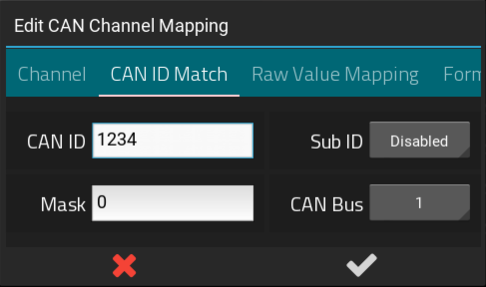
The CAN ID match tab lets you define the CAN ID to match upon, and the CAN bus the data is expected to appear upon. The manufacturer will specify the CAN ID for the channel you are mapping. | |||
[[file:RaceCapture_CAN_mapping_can_id_tab.png|486px]] | |||
* '''CAN ID''': this is the ID of the CAN bus message, in decimal format. | |||
* '''Mask''': This is an optional mask, in decimal format. If set to greater than zero, the Mask will be logically AND'd with the CAN ID for further matching and filtering. | |||
** ''If uncertain, leave this unchanged'' | |||
* '''Sub ID''': If the CAN message specifies the first byte as an additional ID to differentiate messages, specify the value to match here. | |||
* '''CAN Bus''': Select the CAN bus your data is appearing on - CAN 1 or 2, depending on the available CAN ports of your RaceCapture device. | |||
====Defining the mapping==== | |||
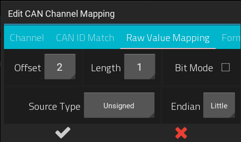
The Raw Value Mapping tab lets you define how to extract the data from the 8 byte CAN message. The manufacturer's CAN documentation will identify this information for channel you are mapping. | |||
[[file:RaceCapture_CAN_mapping_raw_value_mapping.png]] | |||
* '''Offset''': this is the offset where the data appears in the CAN message. An offset of 0 would be used to start at the first byte of the CAN message. | |||
* '''Length''': this represents the length of the value. A length of 1 would be one byte, 2 would represent a two byte or 16 bit word, and so on. | |||
* '''Source Type''': this represents the native encoding of the data. Most typically this is represented as a plain unsigned value, but can appear in other formats. The manufacturer's CAN documentation will identify the data type. Supported native data types: | |||
** Unsigned: the data is provided as an unsigned value. | |||
** Signed: the data is provided as a [https://en.wikipedia.org/wiki/Two%27s_complement two's compliment] signed value. | |||
** Float: the data is provided as a [https://en.wikipedia.org/wiki/IEEE_floating_point IEEE-754 encoded] floating point value | |||
** Sign-Magnitude: the data is provided as a [https://en.wikipedia.org/wiki/Signed_number_representations#Signed_magnitude_representation sign-magnitude] encoded value. | |||
* '''Endian''': This defines Big Endian (Most significant bit / MSB) or Little Endian (Least Significant Bit / LSB) mode, and applies to values where the data length is 2 or higher. The manufacturer's documentation will identify whether the data is encoded in big or little endian format. | |||
* '''Bit Mode''': This allows mapping in cases where the data does not fall on even byte boundaries. For example, you may want to extract a single bit at the offset of 11; in which case you would enable bit mode, then set your offset to 11 with a length of 1. | |||
** ''If uncertain, leave this unchecked, or check the manufacturer's documentation'' | |||
====Defining the Formula==== | |||
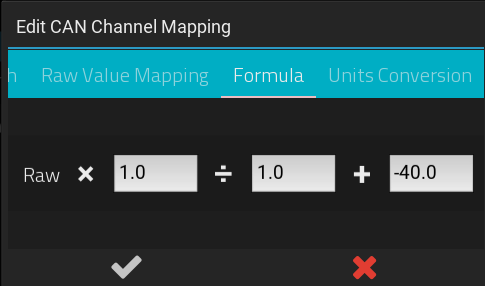
The Formula tab lets you define how to convert the extracted raw value into a meaningful real-world value. | |||
[[file:RaceCapture_CAN_mapping_formula_tab.png]] | |||
The formula is defined as: | |||
Extracted Raw Value X '''multiplier''' ÷ '''divider''' + '''adder''' | |||
Use these fields to specify the conversion formula you wish to apply to the raw value extracted from the CAN message. The manufacturer's documentation will specify the conversion formula. | |||
== | ====Units Conversion==== | ||
[[file:RaceCapture_CAN_mapping_units_conversion_tab.png]] | |||
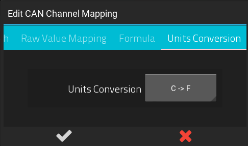
You can optionally apply a common units conversion to the value after it has been processed by the formula. Often the manufacturer will provide the mapping in one form of units - this allows you to retain the original mapping and then convert the units to the desired format. | |||
===Testing your channel=== | |||
When complete with the mapping, press the (check) button and then '''Write''' your configuration back to RaceCapture. You can then go to the dashboard to monitor the current channels and verify you are receiving data as expected. | |||
=== | ===Not getting the expected data?=== | ||
See the [[CAN_Bus_Integration#Troubleshooting|Troubleshooting Guide]] to help understand and identify problems in your CAN mapping and connectivity. | |||
== | ==Lua scripting== | ||
* Applies to: | |||
** RaceCapture/Pro MK2 and newer | |||
** RaceCapture/Apex | |||
** RaceCapture/Track MK2 and newer | |||
For custom mapping that cannot be handled by the direct CAN mapping capabilities, you can map data using the on-board Lua scripting runtime. Here you will be able to apply any formula or custom logic to the data before mapping it to a channel in RaceCapture. | |||
= | ===Reading a CAN message=== | ||
==Reading a CAN message== | |||
You can use the Lua scripting to read and process data from a CAN message. See the [[RaceCapturePro_Lua_Scripting#CAN_Bus_functions|Lua Scripting reference]] for a list of CAN bus functions. | You can use the Lua scripting to read and process data from a CAN message. See the [[RaceCapturePro_Lua_Scripting#CAN_Bus_functions|Lua Scripting reference]] for a list of CAN bus functions. | ||
| Line 64: | Line 280: | ||
print("ID: " ..id .."Data: " ..data[1]) | print("ID: " ..id .."Data: " ..data[1]) | ||
==Mapping to a Virtual Channel== | ===Mapping to a Virtual Channel=== | ||
You can create a virtual channel by using the ''[[RaceCapturePro_Lua_Scripting#Virtual_Channels|addChannel()]]'' lua function. The typical approach involves: | You can create a virtual channel by using the ''[[RaceCapturePro_Lua_Scripting#Virtual_Channels|addChannel()]]'' lua function. The typical approach involves: | ||
| Line 75: | Line 292: | ||
* Example: Set '''MyChannel''' from CAN ID 1234. Data is in the first byte of the message. | * Example: Set '''MyChannel''' from CAN ID 1234. Data is in the first byte of the message. | ||
<pre> | |||
channelId = addChannel("MyChannel", 10) | channelId = addChannel("MyChannel", 10) | ||
setTickRate(10) | setTickRate(10) | ||
| Line 85: | Line 302: | ||
end | end | ||
end | end | ||
</pre> | |||
==CAN integration framework== | ==CAN integration framework== | ||
Below is a script framework to ease mapping of CAN bus data to virtual channels. You can copy the script and modify as you need. This example showcases mapping some of the BMW E46 CAN bus channels | Below is a script framework to ease mapping of CAN bus data to virtual channels. You can copy the script and modify as you need. This example showcases mapping some of the BMW E46 CAN bus channels. | ||
To create your own integration, edit the top portion of the file to match your system's CAN bus configuration and data mapping. | |||
<pre> | <pre> | ||
| Line 99: | Line 319: | ||
CAN_chan = 0 | CAN_chan = 0 | ||
--1 for Big Endian (MSB) mode; 0 for Little Endian mode (LSB) | --1 for Big Endian (MSB) mode; 0 for Little Endian mode (LSB) | ||
be_mode = | be_mode = 0 | ||
--add your virtual channels here | --add your virtual channels here | ||
| Line 162: | Line 382: | ||
setTickRate(tickRate) | setTickRate(tickRate) | ||
</pre> | </pre> | ||
==Reverse Engineering== | |||
Reverse engineering can be a rewarding experience, providing you can log the CAN data stream from the device and compare it against direct measurements on the system. | |||
===Common Approach=== | |||
* Log all messages from the CAN bus | |||
* Directly measure or observe a sensor channel and compare it against changes in the CAN bus data, watching for patterns. | |||
===Example=== | |||
An example for decoding RPM: To detect which CAN message contains RPM, log all CAN messages while simultaneously directly logging RPM, synchronizing the messages and the direct RPM measurement in time. Watch for patterns in the CAN data: any data changing in sync with the direct RPM measurements will be a strong indicator of which CAN message contains RPM data. | |||
Repeat with other sensors of interest, such as steering angle, tempertures, etc. | |||
===Logging Data=== | |||
You can use a commercial CAN data logger, or simply use RaceCapture/Pro's [[CAN_Bus_logger|CAN bus logger script]] to output all messages to the logging window. | |||
=Troubleshooting= | |||
==Check the CAN bus settings== | |||
* Ensure the global CAN enabled option is turned '''on'' on the CAN settings page | |||
* Ensure the baud rate matches the network you're connecting to. | |||
** If you're not certain, check the documentation of the device you're integrating with (ECU, sensor network, etc) | |||
* Ensure the CAN termination is correct for the network you are on. | |||
** Termination is required at both ends of the network; check your manufacturer if termination is enabled inside the device, or if an external jumper is needed. | |||
** '''Note:''' | |||
*** RaceCapture/Pro MK3, RaceCapture/Apex, PodiumConnect, RaceCapture/Track MK3: Termination is software controlled; enabled by default. It can be enabled/disabled in the CAN Bus settings page. | |||
*** RaceCapture/Pro MK2 has termination enabled by default, it can be disabled by disabling the internal jumper | |||
*** RaceCapture/Track (MK1, MK2) - Termination is disabled by default. Termination can be enabled by enabling an internal jumper. | |||
==Check the CAN activity LED== | |||
The CAN activity LED will indicate if CAN data is being received by your RaceCapture system. If it's illuminated, that means RaceCapture is receiving CAN data. | |||
* Applies to: | |||
** RaceCapture/Apex | |||
** RaceCapture/Pro MK3 | |||
==Check the CAN bus you are using (CAN1 or CAN2)== | |||
If you're using a preset, check if the CAN bus you wired matches the CAN bus selected for each channel in the preset. | |||
* Most presets are configured to use CAN1. If you wired your CAN but to CAN2, you will need to switch each channel under presets to CAN2. | |||
==Check the wiring== | |||
* Ensure you have CAN High and CAN Low of the other CAN device wired to the equivalent CAN high and CAN low of RaceCapture. | |||
** If the wires are reversed, try swapping them. | |||
* Check that you have the wires connected correctly per the pinout of your system. | |||
==Check termination on the bus== | |||
Ideally, you should have termination at each end of the bus. Due to the robustness of CAN bus, often termination at one end of the bus is sufficient for correct data transmission. | |||
** RaceCapture/Pro, RaceCapture/Apex and PodiumConnect: Software-controlled termination can be accessed under Setup/CAN bus. | |||
** RaceCapture/Track MK1 and MK2 have no termination on board - termination can be added near the connector. | |||
Ensure that the device at the opposite end of the CAN bus has termination enabled. | |||
* To enable termination, connect a 120 ohm resistor (1/8 to 1/4 W) across the CAN high and CAN low wires. | |||
==Check the other device== | |||
Ensure the setup is correct on the device. Check their manual and software to ensure: | |||
* CAN broadcasting is enabled | |||
* CAN baud rate matches the CAN baud rate your system | |||
** Typical baud rates are 250K, 500K and 1M | |||
* CAN IDs match the IDs you have defined under the CAN channels. | |||
** Some devices have the ability to set an alternate addressing scheme; their documentation will indicate if this is possible. | |||
** Use the [[CAN_Bus_logger|simple logging script]] to display all CAN traffic in the logging window to see if what you are receiving is what you expect. | |||
==CAN bus logger== | |||
* Try using the [[CAN_Bus_logger|simple logging script]] to show any incoming data and that it matches what you expect vs the manufacturer's specifications. | |||
Latest revision as of 09:31, 22 July 2024
Introduction
Mapping an existing CAN bus system can be easy with basic knowledge of CAN mapping, and most importantly - if CAN technical documentation is available for the device in question. Fortunately, ECU and sensor manufacturers are keen on providing documentation as they naturally want their devices as inter-operable as possible.
If documentation isn't available, the problem is just more interesting to someone with the time and skills, and it helps that the CAN bus system is open in terms of it's messaging format and provides simple 8 byte message packets with a numeric identifier, much like an internet IP address.
Prerequisites
To successfully perform a custom CAN integration, it's helpful to have the following knowledge before you get started.
- Basic knowledge of wiring and making wiring connections
- Basic knowledge of CAN bus technology. Here are some some helpful links.
Also, if you need to make a custom mapping because no preset exists for your device:
- Basic understanding of math
- Basic understanding of data represented as bits and bytes
If this appears challenging, get a friend to help and / or jump onto the forums and ask for assistance - another forum member might have mapped the same system as you're working with, or can help you with your particular project.
Preset configurations
Fortunately, we have a growing library of pre-set configurations for different ECUs and sensors. As time goes on, the chances grow that you'll be able to simply click a button and have a quickly working CAN integration.
Wiring CAN bus
Integrating a CAN-enabled device to RaceCapture involves connecting the CAN bus connections to RaceCapture.
Each CAN device has two wires that provides data:
- CAN high (CANH)
- CAN low (CANL)
When you connect the device to the CAN bus, you would connect the CAN high and CAN low wires of the device to the CAN high and CAN low wires of RaceCapture.
Choosing the CAN bus to connect
RaceCapture has multiple CAN bus networks. There is a convention for choosing which CAN bus when connecting a device:
- CAN1 - typically used for ECUs (OBDII and after-market)
- CAN2 and higher - typically used for extended sensor networks, such as AnalogX, TireX, etc.
This approach isolates the extended sensors from the car's ECU, especially important when working with OEM ECU networks.
- Note - this is not a hard and fast rule, but a convention. Advanced users may choose any configuration that meets their needs.
Plug and Play connector system
- Applies to
- RaceCapture/Track MK3
- RaceCapture/Pro MK4
- PodiumConnect MK2
See the full plug and play harness specification
Power + CAN Single interconnect
- Connector: M8 4P, A coding
Male connector pictured
| Pin | Connection | Notes |
|---|---|---|
| 1 | CAN low | White |
| 2 | Power | Red, 9-24v / 1A (~12W) |
| 3 | CAN high | Green |
| 4 | Ground | Black |
Dual CAN + power interconnect
- Connector: M8 6P, A coding
Male connector pictured
| Pin | Connection | Notes |
|---|---|---|
| 1 | CAN1 low | |
| 2 | CAN2 low | |
| 3 | CAN2 high | |
| 4 | Ground | |
| 5 | CAN1 high | |
| 6 | Power | 9-24v / 1A (~12W) |
Molex connector
- Applies to
- RaceCapture/Pro MK3
Both CAN ports are available on the molex connector:
RJ45 connector
- Applies to
- RaceCapture/Pro MK3
- RaceCapture/Pro MK2
This port is typically used for the optional CAN-OBDII interface cable, but can also be used for custom integrations. Both CAN channels are available on the RJ45 connection.
Cabling
You can custom crimp an RJ45 cable, or you can use a standard CAT-5 ethernet cable with RJ45 connectors to integrate with RaceCapture/Pro.
| Connection | RaceCapture/Pro (RJ45 cable) |
|---|---|
| +12v | Brown |
| Ground | Orange/White |
| CAN 1 High | Orange |
| CAN 1 Low | Green/White |
| CAN 2 High | Blue |
| CAN 2 Low | Blue/White |
- Important note for MK2: The +12v connection on the RJ45 is connected internally to the +12v on the terminal block on RaceCapture/Pro MK2. It's recommended you only power via one source - RJ45 or terminal block - if you have both connected at the same time, you may cause back-feeding of power through RaceCapture/Pro, which may cause damage to the unit. Note: RaceCapture/Pro MK3 has internal protection diodes which avoids this issue.
Researching CAN Bus protocol
If you are working to integrate an ECU, first ask the manufacturer for their CAN bus specification. This documentation will provide a breakdown of channels - such as RPM, temperatures and pressures and describe how they appear in the CAN message stream. A good example is the Megasquirt CAN Broadcast Specification.
CAN Bus documentation
The manufacturer provided document will show for each channel the following information:
- Channel: (RPM, Engine Temperature, Throttle Position, etc)
- CAN Identifier: The CAN Identifier for each channel. This may appear in either 11 or the extended 29 bit format. Typically 11 bits are used.
- Offset: where the data starts within the 8 byte CAN message. An offset of 0 means the data starts on the first byte.
- Length: Typically 1 or two bytes
- Scaling: The raw value from the message is often scaled to a real world value. Typically this is provided as a multiplier and adder value, but may also specify a divider.
Big Endian or Little Endian mode
Additionally, the manufacturer will specify if multi-byte (16, 24 or 32 bit) values are presented in Big Endian (MSB (Most Significant Bit)) or Little Endian (LSB (Least Significant Bit)) mode.
BigEndian mode data will have the high byte presented first in the data packet and is typically the most common format.
Big Endian / Little Endian Example:
- Decimal value: 1000
- Hex Value in Big Endian: 0x03E8
- Hex Value in Little Endian: 0xE803
If provided in a CAN message, it might show up as follows in this hypothetical message:
MSB format:
- Offset 1
- Length 2
- Data:
(Hex)     [xx] [03] [E8] [xx] [xx] [xx] [xx] [xx]
(Decimal) [xx] [3] [232] [xx] [xx] [xx] [xx] [xx]
LSB format:
- Offset 1
- Length 2
- Data:
(Hex)     [xx] [E8] [03] [xx] [xx] [xx] [xx] [xx]
(Decimal) [xx] [232] [3] [xx] [xx] [xx] [xx] [xx]
Enabling CAN bus
Once you have the CAN connections wired, you can enable CAN bus on your RaceCapture system. This provides the ability to turn on the CAN bus connectivity at the global level, and allows you to set the baud rate for the individual CAN bus channels.
After making changes, be sure to write your configuration back to your RaceCapture device.
Mapping CAN data to channels
Direct CAN mapping
The direct CAN mapping capabilities will allow easy mapping of 99% of existing CAN based ECUs and sensors. For the outliers, you can map CAN data using the on-board Lua Scripting, allowing for any custom formula or logic.
Adding a channel
- To start, connect to your RaceCapture device and ensure the current configuration is read, or open a previously saved configuration.
- Navigate to the CAN Mapping page.
- Ensure CAN channels is set to on
- Press the (+) button to add your first channel.
Defining the Channel
The first tab will let you define the channel name and sample rate.
- Channel Name: selecting a channel name from the drop-down will pre-set the units, min, max and precision to typical values.
You can customize this by pressing the gear icon to customize:
- Channel Name - Specify the channel name. We recommend formatting the name with CamelCase with a leading capital letter, and no spaces or underscores.
- Units - The unit of measurement for the channel
- Min - The minimum value for the channel
- Max - The maximum value for the channel
- Precision - Sets the number of decimal places for logged and displayed numbers.
- Rate: This sets the rate that RaceCapture will log or broadcast the data for this channel. This rate is independent of the actual rate the CAN data is received. Select a rate that mirrors the expected update rate of the sensor. Example: Engine temperature changes slowly, so select 1Hz. RPM changes quickly; 10-50Hz is ideal.
Defining the CAN ID and bus
The CAN ID match tab lets you define the CAN ID to match upon, and the CAN bus the data is expected to appear upon. The manufacturer will specify the CAN ID for the channel you are mapping.
- CAN ID: this is the ID of the CAN bus message, in decimal format.
- Mask: This is an optional mask, in decimal format. If set to greater than zero, the Mask will be logically AND'd with the CAN ID for further matching and filtering.
- If uncertain, leave this unchanged
- Sub ID: If the CAN message specifies the first byte as an additional ID to differentiate messages, specify the value to match here.
- CAN Bus: Select the CAN bus your data is appearing on - CAN 1 or 2, depending on the available CAN ports of your RaceCapture device.
Defining the mapping
The Raw Value Mapping tab lets you define how to extract the data from the 8 byte CAN message. The manufacturer's CAN documentation will identify this information for channel you are mapping.
- Offset: this is the offset where the data appears in the CAN message. An offset of 0 would be used to start at the first byte of the CAN message.
- Length: this represents the length of the value. A length of 1 would be one byte, 2 would represent a two byte or 16 bit word, and so on.
- Source Type: this represents the native encoding of the data. Most typically this is represented as a plain unsigned value, but can appear in other formats. The manufacturer's CAN documentation will identify the data type. Supported native data types:
- Unsigned: the data is provided as an unsigned value.
- Signed: the data is provided as a two's compliment signed value.
- Float: the data is provided as a IEEE-754 encoded floating point value
- Sign-Magnitude: the data is provided as a sign-magnitude encoded value.
- Endian: This defines Big Endian (Most significant bit / MSB) or Little Endian (Least Significant Bit / LSB) mode, and applies to values where the data length is 2 or higher. The manufacturer's documentation will identify whether the data is encoded in big or little endian format.
- Bit Mode: This allows mapping in cases where the data does not fall on even byte boundaries. For example, you may want to extract a single bit at the offset of 11; in which case you would enable bit mode, then set your offset to 11 with a length of 1.
- If uncertain, leave this unchecked, or check the manufacturer's documentation
Defining the Formula
The Formula tab lets you define how to convert the extracted raw value into a meaningful real-world value.
The formula is defined as: Extracted Raw Value X multiplier ÷ divider + adder
Use these fields to specify the conversion formula you wish to apply to the raw value extracted from the CAN message. The manufacturer's documentation will specify the conversion formula.
Units Conversion
You can optionally apply a common units conversion to the value after it has been processed by the formula. Often the manufacturer will provide the mapping in one form of units - this allows you to retain the original mapping and then convert the units to the desired format.
Testing your channel
When complete with the mapping, press the (check) button and then Write your configuration back to RaceCapture. You can then go to the dashboard to monitor the current channels and verify you are receiving data as expected.
Not getting the expected data?
See the Troubleshooting Guide to help understand and identify problems in your CAN mapping and connectivity.
Lua scripting
- Applies to:
- RaceCapture/Pro MK2 and newer
- RaceCapture/Apex
- RaceCapture/Track MK2 and newer
For custom mapping that cannot be handled by the direct CAN mapping capabilities, you can map data using the on-board Lua scripting runtime. Here you will be able to apply any formula or custom logic to the data before mapping it to a channel in RaceCapture.
Reading a CAN message
You can use the Lua scripting to read and process data from a CAN message. See the Lua Scripting reference for a list of CAN bus functions.
Example reading and printing the ID and first byte of a CAN message:
id, ext, data = rxCAN(0, 100)
print("ID: " ..id .."Data: " ..data[1])
Mapping to a Virtual Channel
You can create a virtual channel by using the addChannel() lua function. The typical approach involves:
- Set up the channel. Example "EngineTemp"
- Read a CAN message
- Extract a value from the data fields
- Scale the extracted value to a real world value (Example: Degrees F)
- Set the virtual channel with the scaled value
- Example: Set MyChannel from CAN ID 1234. Data is in the first byte of the message.
 channelId = addChannel("MyChannel", 10)
 setTickRate(10)

 function onTick()
   id, ext, data = rxCAN(0)
   if id == 1234 then
     setChannel(channelId, data[1])
   end
 end
CAN integration framework
Below is a script framework to ease mapping of CAN bus data to virtual channels. You can copy the script and modify as you need. This example showcases mapping some of the BMW E46 CAN bus channels.
To create your own integration, edit the top portion of the file to match your system's CAN bus configuration and data mapping.
--This example configured for E46 CAN

--how frequently we poll for CAN messages
tickRate = 30
--the CAN baud rate
CAN_baud = 500000
--CAN channel to listen on. 0=first CAN channel, 1=second
CAN_chan = 0
--1 for Big Endian (MSB) mode; 0 for Little Endian mode (LSB)
be_mode = 0

--add your virtual channels here
tpsId = addChannel("TPS", 10, 0, 0, 100, "%")
tempId = addChannel("EngineTemp", 1, 0, 0, 200, 'C')
oilTempId = addChannel("OilTemp", 1, 0, 0, 200, 'C')
rpmId = addChannel("RPM", 10, 0, 0, 10000)

--customize here for CAN channel mapping
--format is: [CAN Id] = function(data) map_chan(<channel id>, data, <CAN offset>, <CAN length>, <multiplier>, <adder>)
CAN_map = {
[809] = function(data) map_chan(tpsId, data, 6, 1 , 0.392156863, 0) map_chan_le(tempId, data, 2, 1 , 0.75, -48.373) end,
[1349] = function(data) map_chan(oilTempId, data, 5, 1, 1, -48.373) end,
[790] = function(data) map_chan(rpmId, data, 3, 2, 0.15625, 0) end
}

function onTick()
    processCAN(CAN_chan)
end

--===========do not edit below===========
function processCAN(chan)
    repeat
        local id, e, data = rxCAN(chan)
        if id ~= nil then
            local map = CAN_map[id]
            if map ~= nil then
                map(data)
            end
        end
    until id == nil
end

--Map CAN channel, little endian format
function map_chan_le(cid, data, offset, len, mult, add)
    offset = offset + 1
    local value = 0
    local shift = 1
    while len > 0 do
        value = value + (data[offset] * shift)
        shift = shift * 256
        offset = offset + 1
        len = len - 1
    end
    setChannel(cid, (value * mult) + add)
end

--Map CAN channel, big endian format
function map_chan_be(cid, data, offset, len, mult, add)
    offset = offset + 1
    local value = 0
    while len > 0 do
        value = (value * 256) + data[offset]
        offset = offset + 1
        len = len - 1
    end
    setChannel(cid, (value * mult) + add)
end

map_chan = (be_mode == 1) and map_chan_be or map_chan_le
initCAN(CAN_chan, CAN_baud)
setTickRate(tickRate)
Reverse Engineering
Reverse engineering can be a rewarding experience, providing you can log the CAN data stream from the device and compare it against direct measurements on the system.
Common Approach
- Log all messages from the CAN bus
- Directly measure or observe a sensor channel and compare it against changes in the CAN bus data, watching for patterns.
Example
An example for decoding RPM: To detect which CAN message contains RPM, log all CAN messages while simultaneously directly logging RPM, synchronizing the messages and the direct RPM measurement in time. Watch for patterns in the CAN data: any data changing in sync with the direct RPM measurements will be a strong indicator of which CAN message contains RPM data.
Repeat with other sensors of interest, such as steering angle, tempertures, etc.
Logging Data
You can use a commercial CAN data logger, or simply use RaceCapture/Pro's CAN bus logger script to output all messages to the logging window.
Troubleshooting
Check the CAN bus settings
- Ensure the global CAN enabled option is turned 'on on the CAN settings page
- Ensure the baud rate matches the network you're connecting to.
- If you're not certain, check the documentation of the device you're integrating with (ECU, sensor network, etc)
- Ensure the CAN termination is correct for the network you are on.
- Termination is required at both ends of the network; check your manufacturer if termination is enabled inside the device, or if an external jumper is needed.
- Note:
- RaceCapture/Pro MK3, RaceCapture/Apex, PodiumConnect, RaceCapture/Track MK3: Termination is software controlled; enabled by default. It can be enabled/disabled in the CAN Bus settings page.
- RaceCapture/Pro MK2 has termination enabled by default, it can be disabled by disabling the internal jumper
- RaceCapture/Track (MK1, MK2) - Termination is disabled by default. Termination can be enabled by enabling an internal jumper.
Check the CAN activity LED
The CAN activity LED will indicate if CAN data is being received by your RaceCapture system. If it's illuminated, that means RaceCapture is receiving CAN data.
- Applies to:
- RaceCapture/Apex
- RaceCapture/Pro MK3
Check the CAN bus you are using (CAN1 or CAN2)
If you're using a preset, check if the CAN bus you wired matches the CAN bus selected for each channel in the preset.
- Most presets are configured to use CAN1. If you wired your CAN but to CAN2, you will need to switch each channel under presets to CAN2.
Check the wiring
- Ensure you have CAN High and CAN Low of the other CAN device wired to the equivalent CAN high and CAN low of RaceCapture.
- If the wires are reversed, try swapping them.
- Check that you have the wires connected correctly per the pinout of your system.
Check termination on the bus
Ideally, you should have termination at each end of the bus. Due to the robustness of CAN bus, often termination at one end of the bus is sufficient for correct data transmission.
- RaceCapture/Pro, RaceCapture/Apex and PodiumConnect: Software-controlled termination can be accessed under Setup/CAN bus.
- RaceCapture/Track MK1 and MK2 have no termination on board - termination can be added near the connector.
Ensure that the device at the opposite end of the CAN bus has termination enabled.
- To enable termination, connect a 120 ohm resistor (1/8 to 1/4 W) across the CAN high and CAN low wires.
Check the other device
Ensure the setup is correct on the device. Check their manual and software to ensure:
- CAN broadcasting is enabled
- CAN baud rate matches the CAN baud rate your system
- Typical baud rates are 250K, 500K and 1M
- CAN IDs match the IDs you have defined under the CAN channels.
- Some devices have the ability to set an alternate addressing scheme; their documentation will indicate if this is possible.
- Use the simple logging script to display all CAN traffic in the logging window to see if what you are receiving is what you expect.
CAN bus logger
- Try using the simple logging script to show any incoming data and that it matches what you expect vs the manufacturer's specifications.

